

As my shop moves past covering more than 50(!) unique consoles and handhelds it’s becoming increasingly rare to see or find a system I have not worked on let alone laid eyes on before… But such is the case with the Vectrex.
This one came to my attention through friends of ours who had one growing up and had recently discovered it had been kept in storage but mentioned it was not working properly. They knew I worked on all kinds of retro hardware/systems so after talking a bit we figured it would be worth me taking a look at it to see if the issue was fixable or not.
We met up to look over the unit before I took it home to the shop and while it was clear the unit was powering on, all that was visible on the screen was a single white dot, about 1/3 up from the bottom and slightly to the left. This dot faded in and out with the brightness knob but the reset button didn’t do anything and the behavior didn’t change with or without a cart inserted (I know these have a built-in game). I packed it up safely for the trip home along with a game to test and controller that we believed was in working condition.
As someone who has only sparingly worked on CRT’s before (I RGB modded one, recapped the PSU in another) I’m still quite anxious with working near them or dealing with discharging tubes. While this is a small tube I was advised it should still be discharged before use as the only practical way to work on the power board is to unplug the anode cap and separate the board from the tube and shell entirely.
After removing the rear shell with 6 bolts I attached some 16 AWG wire to my insulated flathead screwdriver, tied it off to common ground on the chassis and carefully pried and made contact with the anode clips and… nothing happened. Not a pop, crack or any visible signs of charge left. Just to be sure I repeated this several times and nothing, so I carefully pinched and removed the cap without issue.
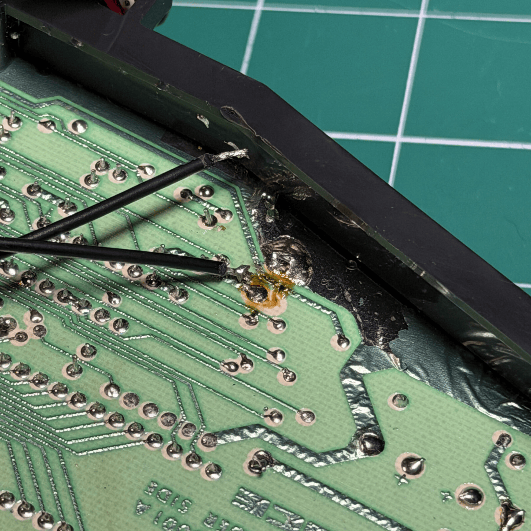
With that part out of the way it was just a matter of documenting (via photos) all the connections from board to board plus the power board to CRT neck board and made a list of what to plug back in via reverse order when reassembling this. During the process of disconnecting everything I discovered a broken ground strap tying power and logic boards together, and both joints for the reset button were completely broken off and separated from the logic board.
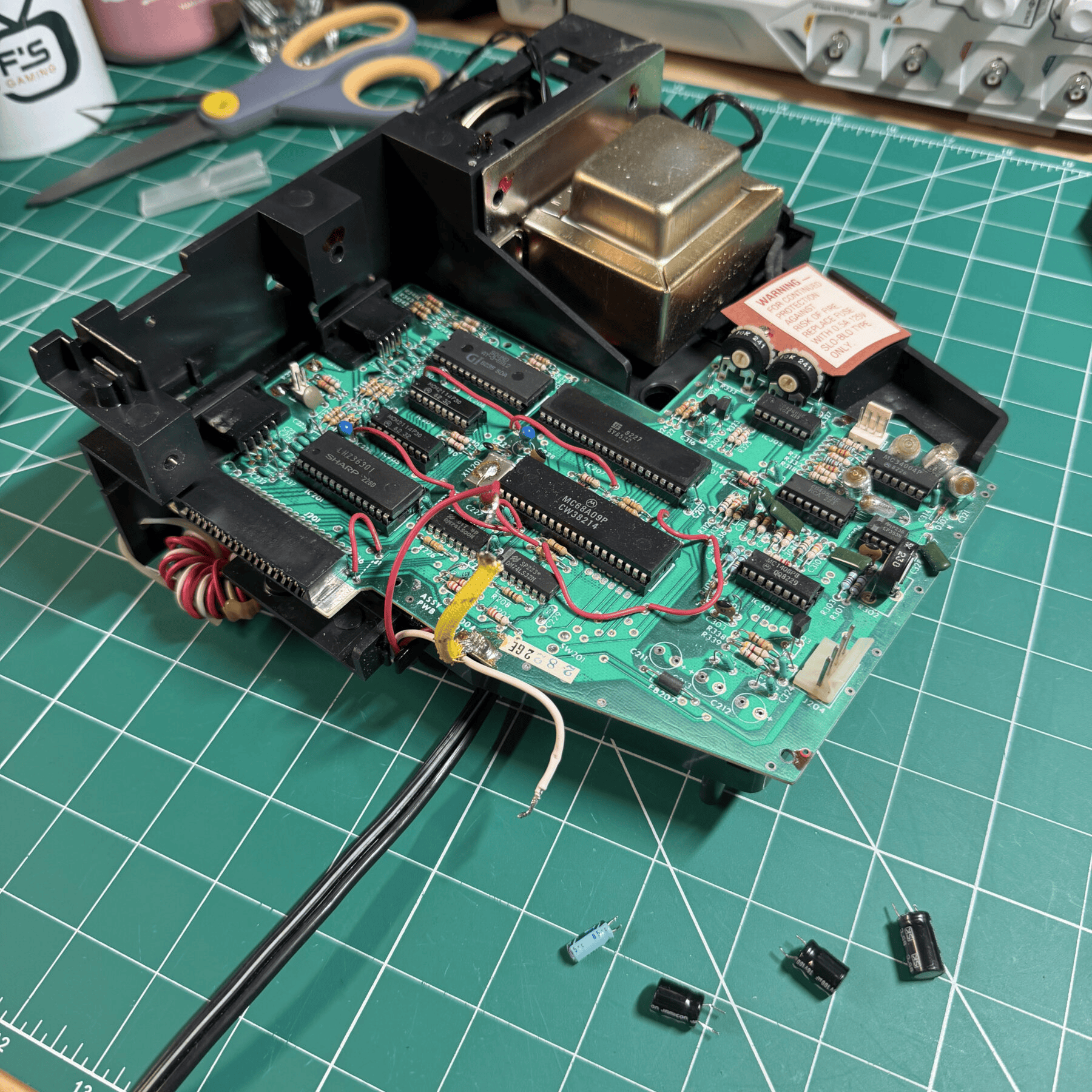
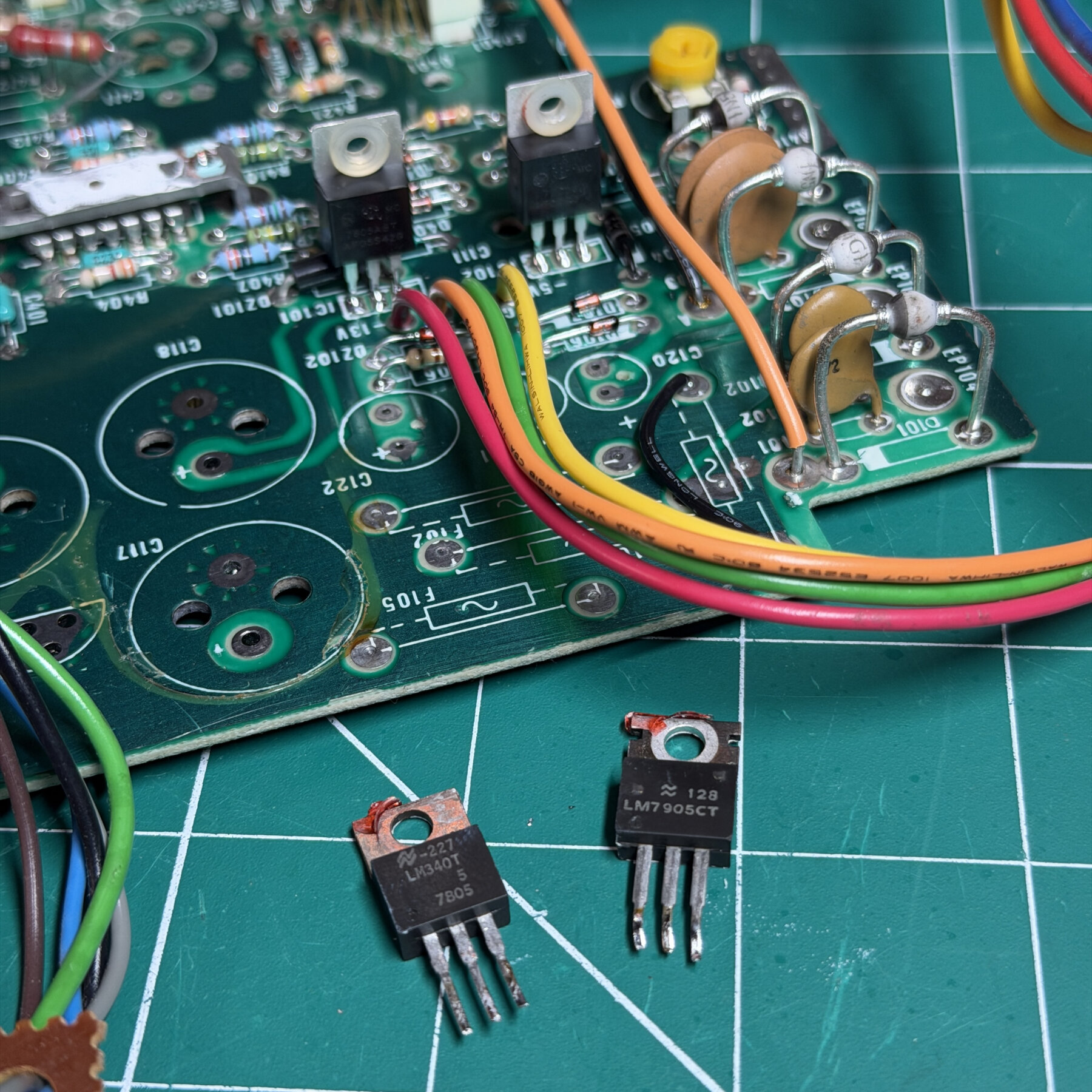
With everything disconnected I was able to pull the power board out completely and the logic board with speaker/plastic frame as well. My plan of attack was to deep clean both boards and the inside, remove and clean and reseat all chips on the logic board, test and replace both voltage regulators and replace all electrolytic capacitors with a Console5 kit.
I figured I would tackle each board separately so I began with the logic board first as it only had 4 capacitors present so the recap would be quick, and I knew with my tools I could remove the chips easily so I did exactly that… desoldered the 4 electrolytics and safely removed all socketed chips and then deep cleaned the board and sockets with duster and 99% ISO, installed the new caps and soldered them in and then re-socketed all the chips after cleaning the pins thoroughly. I then turned my attention to the broken off reset button wires, cleaned and prepped the area then reflowed both connections and confirmed they were secure. That wrapped up the work on the logic board so I set that aside.

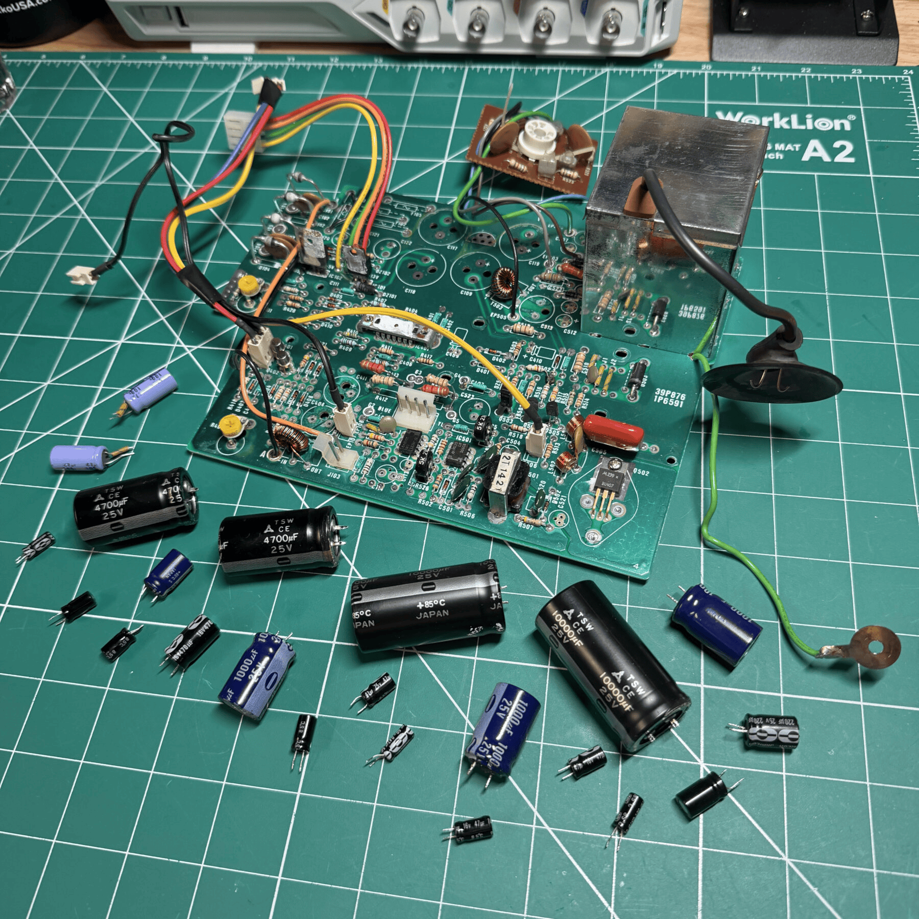
Next up was the power board which contained most of the work. A good number of caps (20+) and a very large heatsink to contend with (some of the caps are under there). Since I wanted to replace both regulators that were attached to the heatsink anyways it had to get removed so I carefully unscrewed the regulators and bent outwards, then unscrewed the heatsink from the board and lifted carefully. This huge heatsink is not just for the regulators though it’s also for a chip located underneath, which cannot ground out to the heatsink so it’s very important to keep the thermal barrier sheet intact on that plus the insulated sheet on the back of the 7905 (or replace them).
Once the heatsink was removed I found 2 more capacitors so I started removing them all with my Hakko gun. I had read some postings of other modders mention the plated holes can be delicate but I had no issues with the recap at all, they all removed super clean with no issue and the plated through holes were completely intact and connected to both sides of the PCB on every single one. I did observe some really bad leaking on several of the large and midsize caps so in those areas I checked the traces and cleaned up the plated areas and mask before the full board clean and installation of new caps.
All the new caps went on without issue and I then desoldered and removed the 7805 and 7905, put the new regulators in place and reinstalled the heatsink with some new thermal paste all while ensuring to reinstall the insulation and plastic screw rings.
I then went through the process of reinstalling both logic and power boards and connecting everything back up one connector at a time while also checking over and reflowing then toning out each wire one by one. I found a few joints on the neck board to power board connector that were dodgy, so I focused on those in particular. With all connections restored (including the broken ground strap) I gave it a quick dead/alive test and I saw the CRT spring to life and display the splash screen with sound and boot the test game “Rip Off”! I did a little more cleaning on the neck board area and then reinstalled a zip tie that secures it to the tube.
The 6 outer bolts went back in place and I cleaned the outer shell carefully and put my service sticker on the bottom (after confirming they were ok with it present) and set it up on the bench for more testing. I observed some really strong audio buzzing but I had already read all about this issue and how it’s a design flaw fixable with ‘buzz-off’ kit installs but they are keeping things stock so left that alone. The built-in game ‘Mine Storm’ played perfectly and I spent even more time with Rip Off as it had the overlay present and confirmed full operation and let it run for a good period of time. I initially thought the controller or controller port was bad but I quickly figured out that unlike most systems the left port is not in fact Player 1, its Player 2 so I moved it to the correct right-side port and the controller worked perfect 🤦♂️
I was pleasantly surprised to see this full refurbishment bring the Vectrex back to life! Dealing with shipping on these would probably be incredibly risky so not sure how many more I’ll ever see come into my shop for service but very cool to get my hands on this piece of tech I had only ever read about at least once!