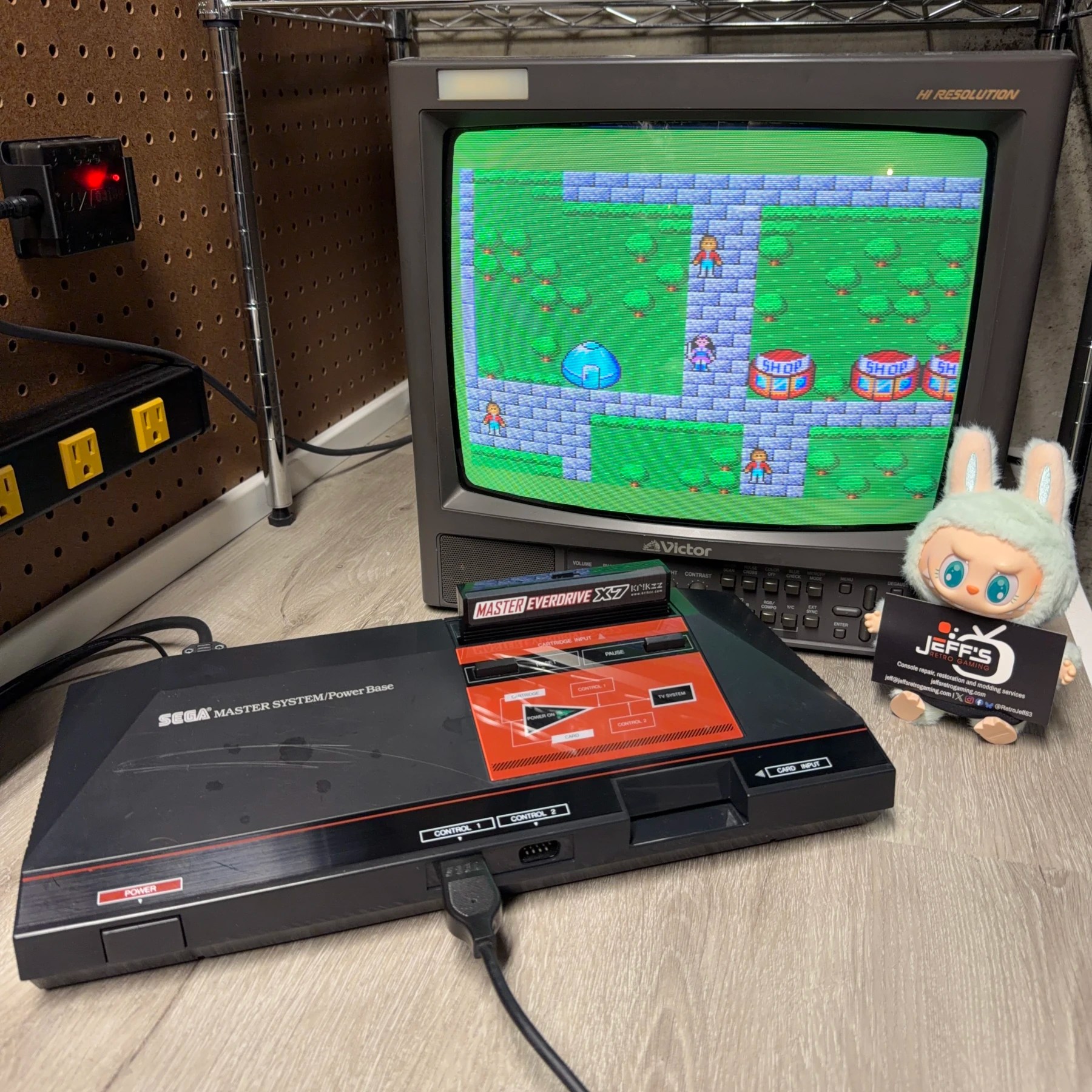
Many years ago on one of my regular trips into a local retro shop (who often generously gifts me free consoles, parts, etc.) I was asked if I wanted this SMS. All I was told is it would not power on, no signs of life. While I often turn away common systems I already have tons of you don’t see a LOT of SMS around these parts and I knew I had to at least give it a shot.
Fast forward to a few weeks later I popped it open and first thing I tested was the 7805 regulator. Immediately tested bad as I was reading 9V in at the input pin but 0V on the output pin (should be 5V). I have a huge stock of brand new 7805 so I swapped one in and it powered up immediately. Thats honestly one of the easiest possible fixes for a system like this. Since that time I have found 2 other customer SMS with a bad/dead 7805 so I don’t waste time messing with them and replace them on EVERY SMS I see in the shop, at no cost and no questions asked.
Anyways, even with it fixed it sat under my bench for years as I already own a model 1 SMS and I planned to eventually refurbish it fully and sell it. The opportunity came up when a mutual on Twitter mentioned they always wanted one and I offered this along with a nice refurb and upgrade. With them on board I set aside a little time and got this system all decked out for its new home!
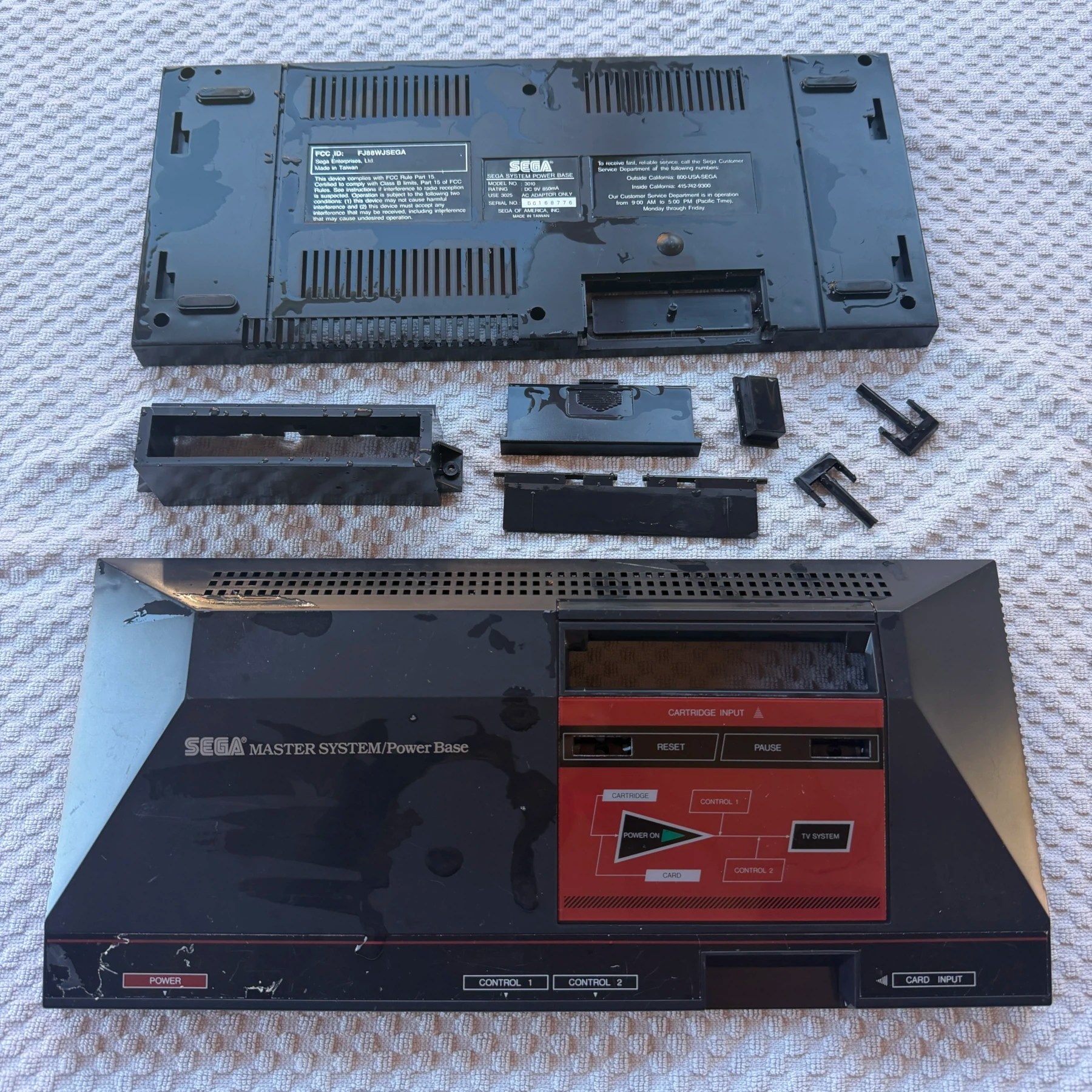
The system was pretty filthy inside and out just covered in dust everywhere and the original trim plastic wrap was peeling heavily from the left front corner. I took all the internals out and soaked the shell and plastic parts in the wash, then scrubbed and set aside to dry.
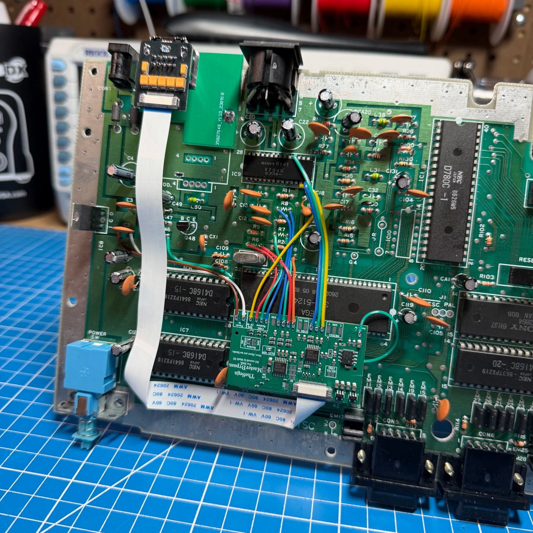
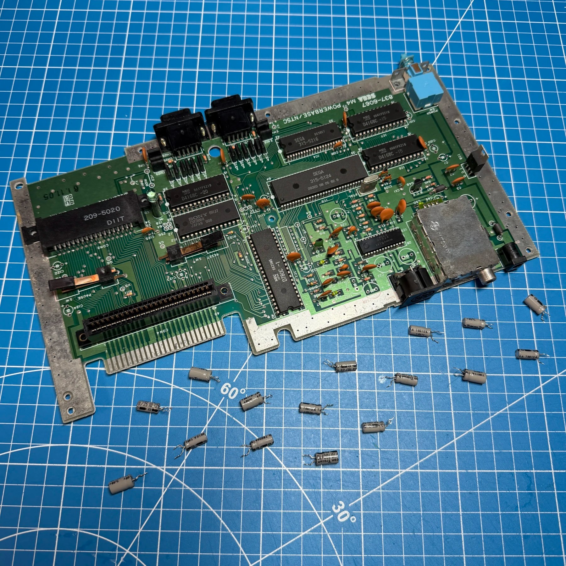
While the mainboard was out I removed all the capacitors and deep cleaned the board on both sides with some 99% ISO and a microfiber. I then checked the Master Bypass guide for any caps that will just be removed during install anyways and since there are none on this 7040-encoder revision I proceeded to install all new caps from the Console5 kit.
Next up was prepping for the bypass install so that meant removing 3 resistors for RGB and the RF modulator which is where the new 10-pin DIN will sit. With those components removed its really just a matter of securing the Bypass board above the 5216 chip (with some heavy duty 3M double sided tape!) and wiring it up to all the necessary points. For the 10-pin DIN install I find it best to drop the board into the lower shell, place the alignment board and DIN inside and then drop the top shell on and move the DIN into perfect place from the access hole using tweezers. If you then carefully remove the top you can make some marks on the DIN border and that will help you line it all up. Depth is the most important here because if you place the board and DIN directly over the old modular through-holes it causes the DIN to sit quite far into the shell. This can be a huge problem because there are a wide variety of RGB cable makers out there and the hoods on many will not slide too far into the shell. If you leave the DIN sitting off the back you can still make it rock solid with a nice bead around 3 sides but get it very close to the outer shell so any cable should insert fully no problem!
With the kit all wired up I temporarily seated the regulator in to give it a test but had one issue… no sound! I knew sound was working before so figured I missed a jumper or did something wrong on the kit. After looking all over the bypass board I realized the issue, somehow the small ceramic cap on audio in trace had broken/fallen off! (take a look at the above bypass install photo and you should be able to spot it!) Not sure when this had happened, but I was able to snag a spare from my cap binder and get it installed… sound was now working and everything looked good, phew 🙏
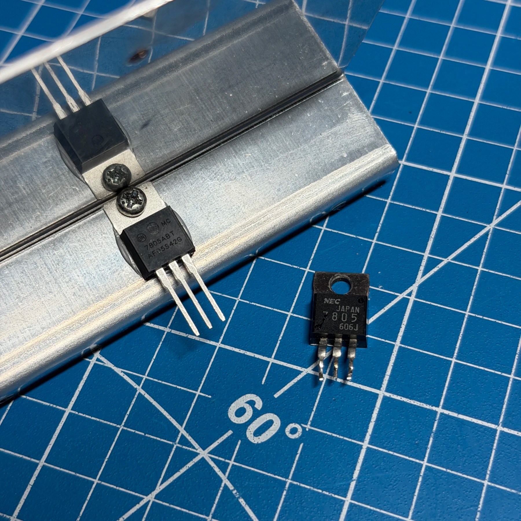
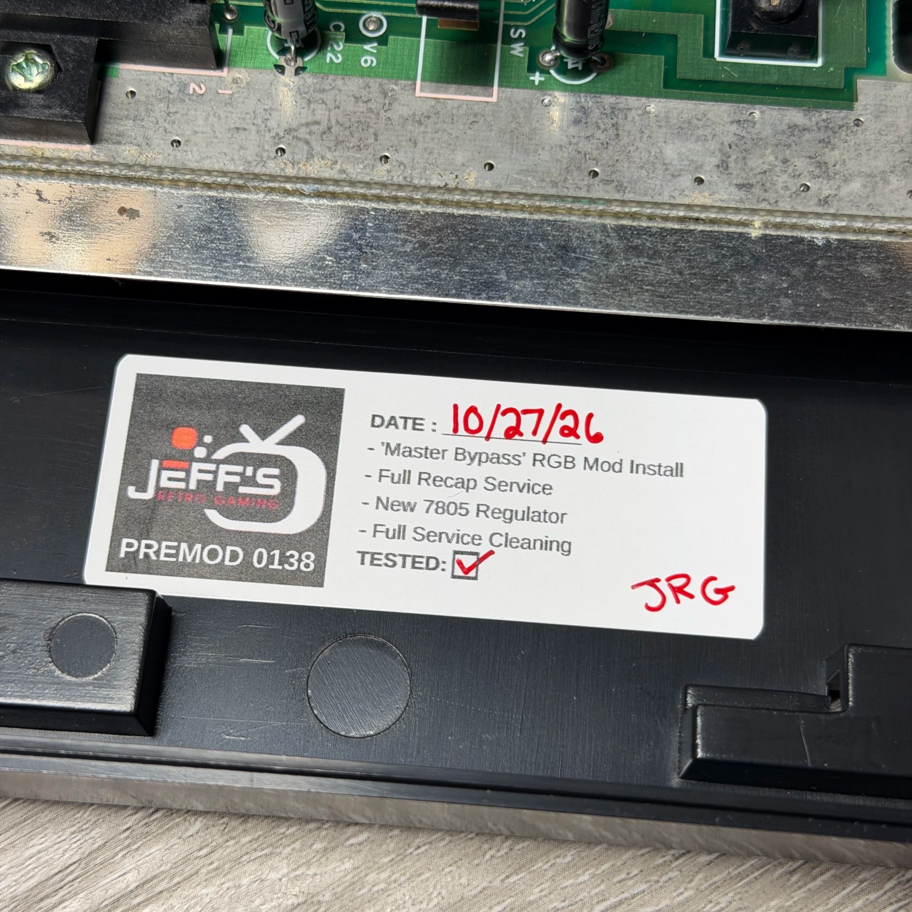
With the bypass, recap and cleaning all done I just needed to put some fresh thermal paste on the back of the new regulator, screw it in to heatsink and solder in place one final time. On this revision it’s much easier to secure it to the heatsink then screw that to board and solder the 3 regulator legs in last than the other way around. That is because the gap to reach in and screw the regulator to the heatsink is VERY tight once it’s dropped onto the mainboard. I also gave the reset and pause button switches a quick cleaning and added my JRG sticker and closed the shell up.
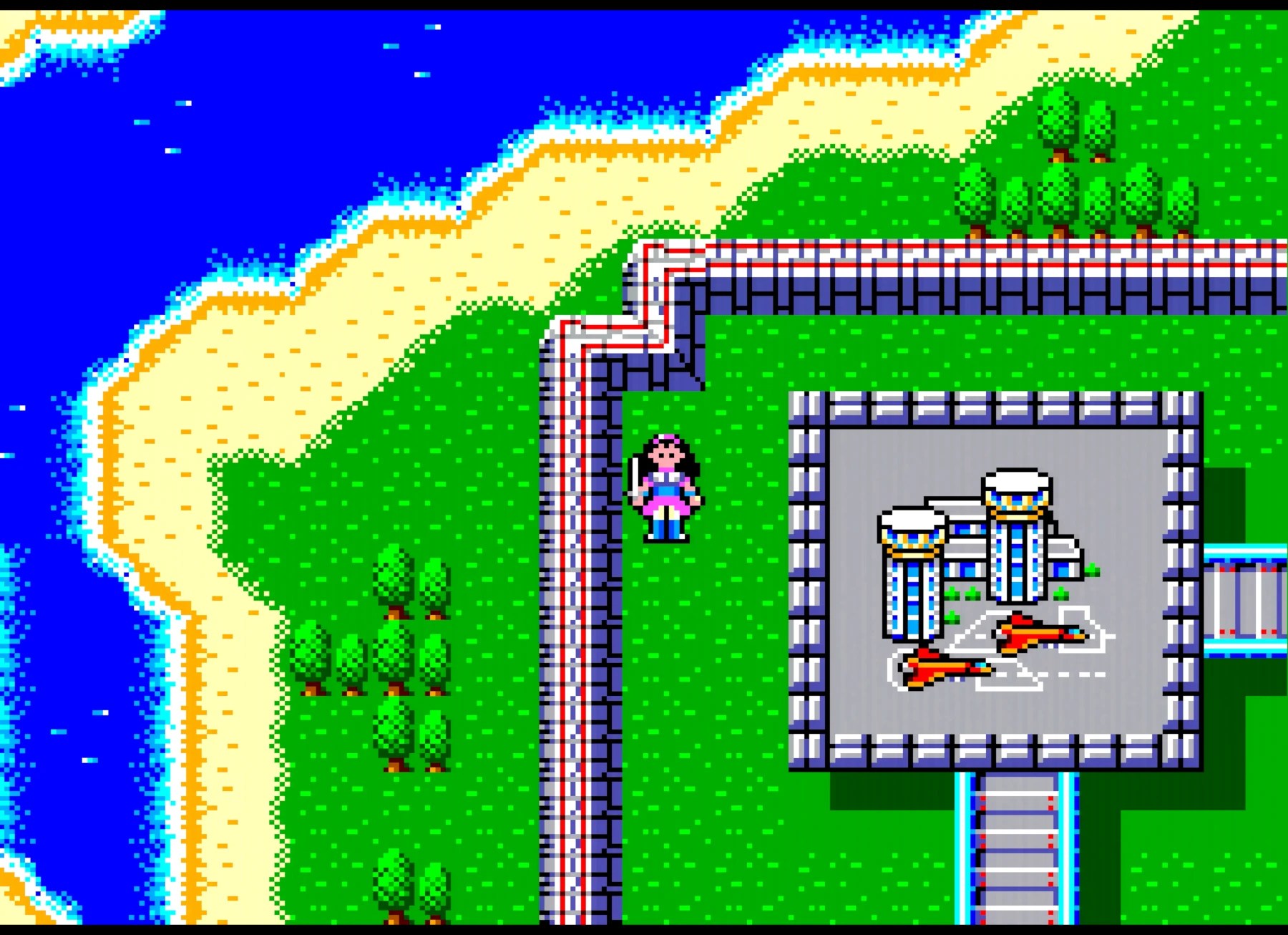
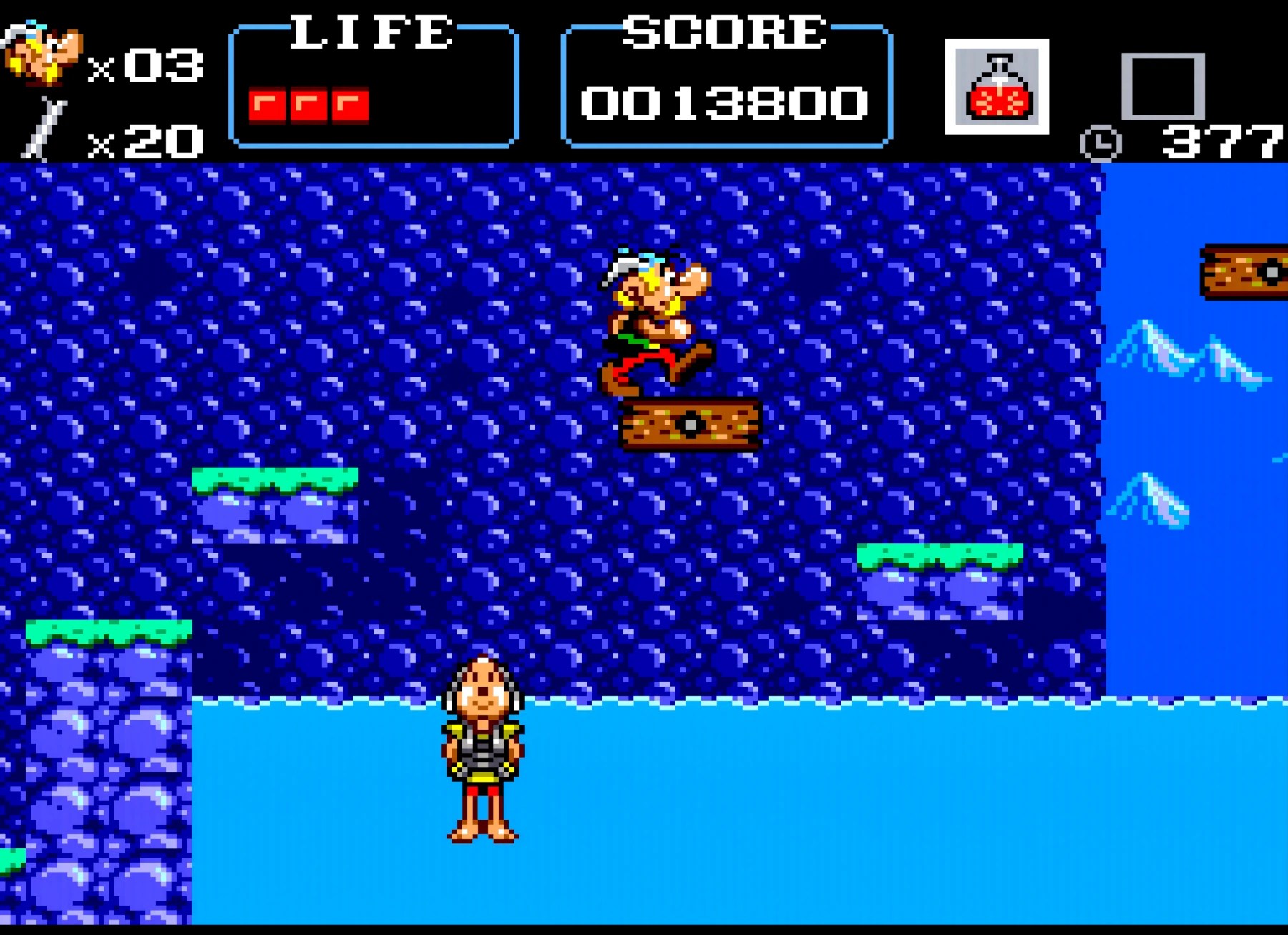
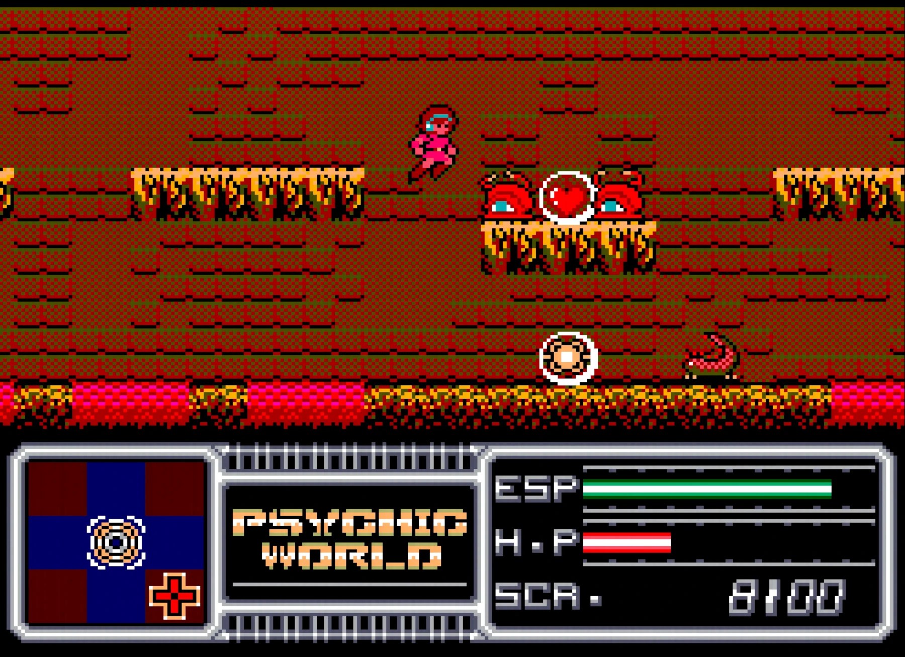
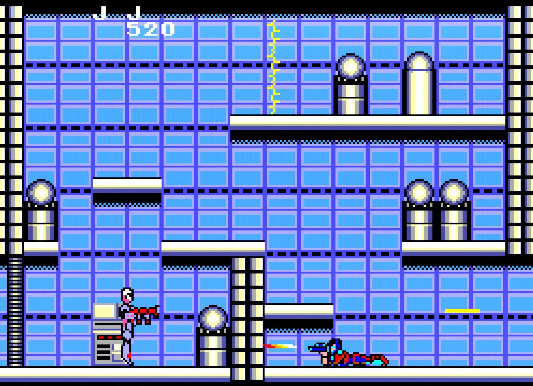
While there are still visible jailbars in the solid color areas it’s a huge improvement over the stock output and only really noticeable on an upscaler like my RetroTink, not observable on a CRT/PVM display. I got some 4K captures (seen below 👇) to share and then gave the entire outer shell one nice coat of UV protectant and peeled the messed-up plastic off the front. For that part, my heat gun at 150C and gently pulling did the trick.
There are some noticeable scratches on the top main panel but not a ton you can do about that without sanding/buffing and ruining the texture further so I decided to leave as-is. Overall, compared to before where it was not powering on and was filthy it looks great and now outputs a much cleaner image!
Glad this SMS will be in its new home soon and hopefully finds a lot of use!