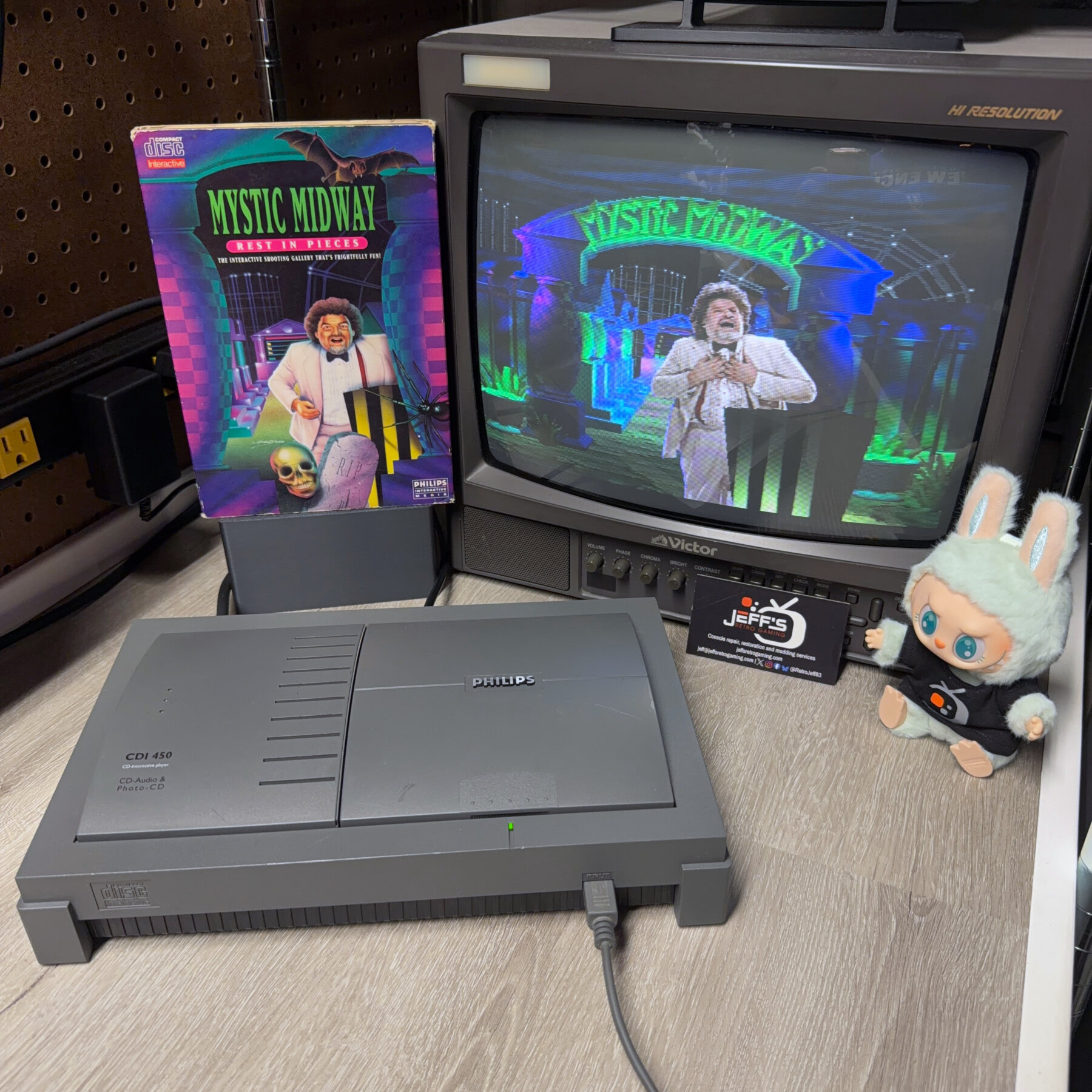
Oh look another CDI 450! Well this time it’s actually a Philips 450 unlike the last one that was a Goldstar but functionality wise and board layout wise I could not honestly tell you any notable differences. I’m assuming they share all the same internals and just rebadge/brand the outer shell 🤷♂️
Either way this one came in for the EXACT same work as the last one – RGB mod (using Mobius Strip Tech RGB Board), new Timekeeper chip, full recap and full-service cleaning!
Since the last RGB mod install I had some 9 din breakout boards made at OshPark for a faster and cleaner install on the AV output. However, I found that it still would not allow complete flush closure of the top shell with this breakout board installed. I have the din pushed as far back and tight against the rear shell wall as possible so I started slowing shaving the area above the rear edge of the din board until the lid would properly close but by that point i had broken through into the DVC slot area. So at that point to be a cleaner finish I just fully cut through that corner at two sharp 90-degree angles to allow the board to have complete clearance around the top and three sides.
This is fine since the cut is invisible to the end user as its hidden inside the DVC slot and the breakout board still allows a cleaner and faster wire job to the DIN. If anyone uses this board and doesn’t cut the area above it that top shell will not naturally drop down perfectly flush/flat without any pressure and IMO that is unacceptable so in this case the tiny shell modification is easily justified 👍

Customer chose full-service cleaning so I got to work disassembling and soaking/washing the shell and plastic parts and setting out to dry overnight. Not much to the plastic component disassembly except the metal tray lid pins can be annoying to get out and I found the power button is clamped on the bottom side of the mechanism so I had to pry it from underneath carefully before lifting that out to get to motherboard.
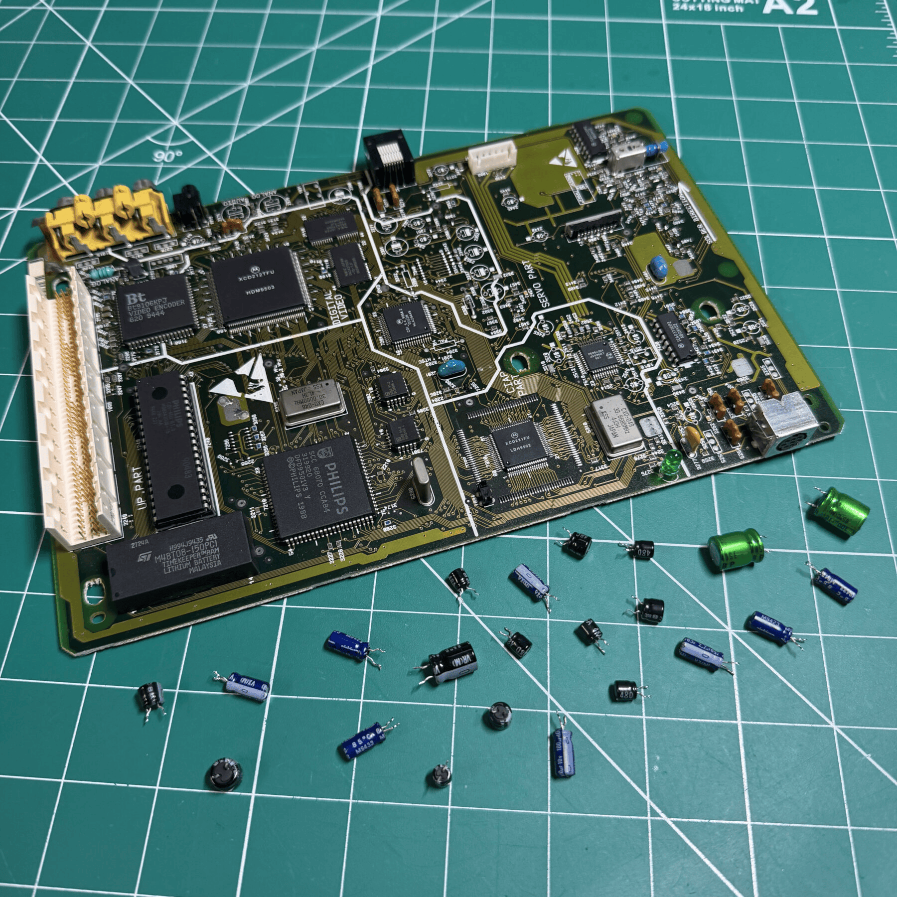
With the shell drying, I made quick work of the caps with my Hakko and then wiped the board down top and bottom side. Something about the finish on these CDI boards always feels very premium compared to a lot of consoles of the era. Its got a nice textured finish and most are in great shape even today, one of the nicest parts about working on these. Once board was cleaned I installed all the new caps from a Console5 kit. I then moved my attention to the Timekeeper. Again, using the Hakko I desoldered the old chip, cleaned under it and soldered the replacement in.
In order to prep for the RGB mod I had to desolder the RCA jacks for video/audio and carefully cut out the composite port, then make some modifications to the metal shielding in that corner and scrape/prep the topside to solder the new 9 pin din in place as the customer had sent that with the kit and wanted to use this CDI with standard Genesis 2 Scart cables.


I protected a via we didn’t want to ground out to the din with some Kapton tape, reassembled the board inside the bottom shell with shield and held the new din in place so it was aligned perfectly and pushed back against the rear shell as tight as possible. Once in place, I soldered in a nice large fillet around it and then swapped from my K tip to my small chisel tip to solder on the DIN breakout board.
While I was working in the AV out area I decided to just wire up Audio Left & Right, Composite Video and 5V points to the din. You don’t have to wire up composite if you plan to only use RGB but this gives you some flexibility if you ever want to use a standard genesis composite cable on say a CRT so I always do this.
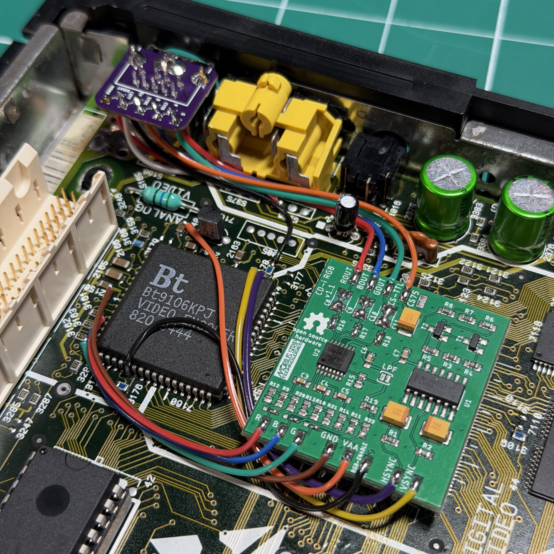
With the AV out area done I then located all the points I need to wire into the RGB board and attached my wires to the encoder or nearby points, then applied some sticky back tape and placed the RGB board on top of the neighboring chip. All of the previously done connections then get soldered to the RGB board and since the customer wants to use genesis cables the next step is to remove 3 caps and 3 resistors from the board and bridge 3 sets of jumpers near R/G/B in.
If using the Genesis 2 cables you then wire up the R/G/B and Sync with Sync going to CS-TTL. If you wanted to use an 8-pin din and cable with no components you would just leave the RGB board alone and instead wire Sync to CS75.
With all the wires done, it was time to quickly test output and I was able to confirm a nice clean RGB image and composite video (as well as audio with both). Before signing off on the console I also booted up a few games, saved data then unplugged for a while and checked to confirm Timekeeper was retaining saves and date/time.
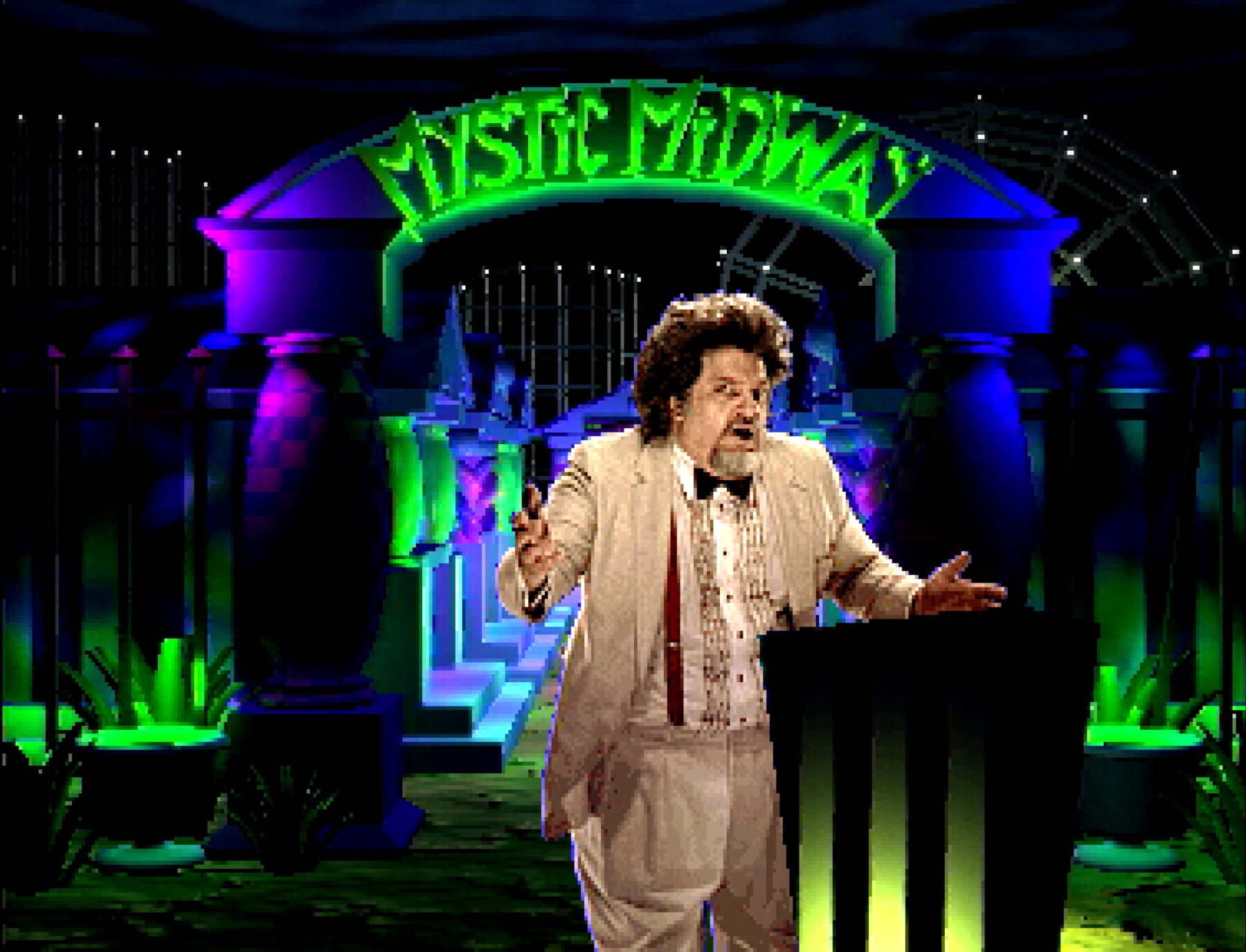
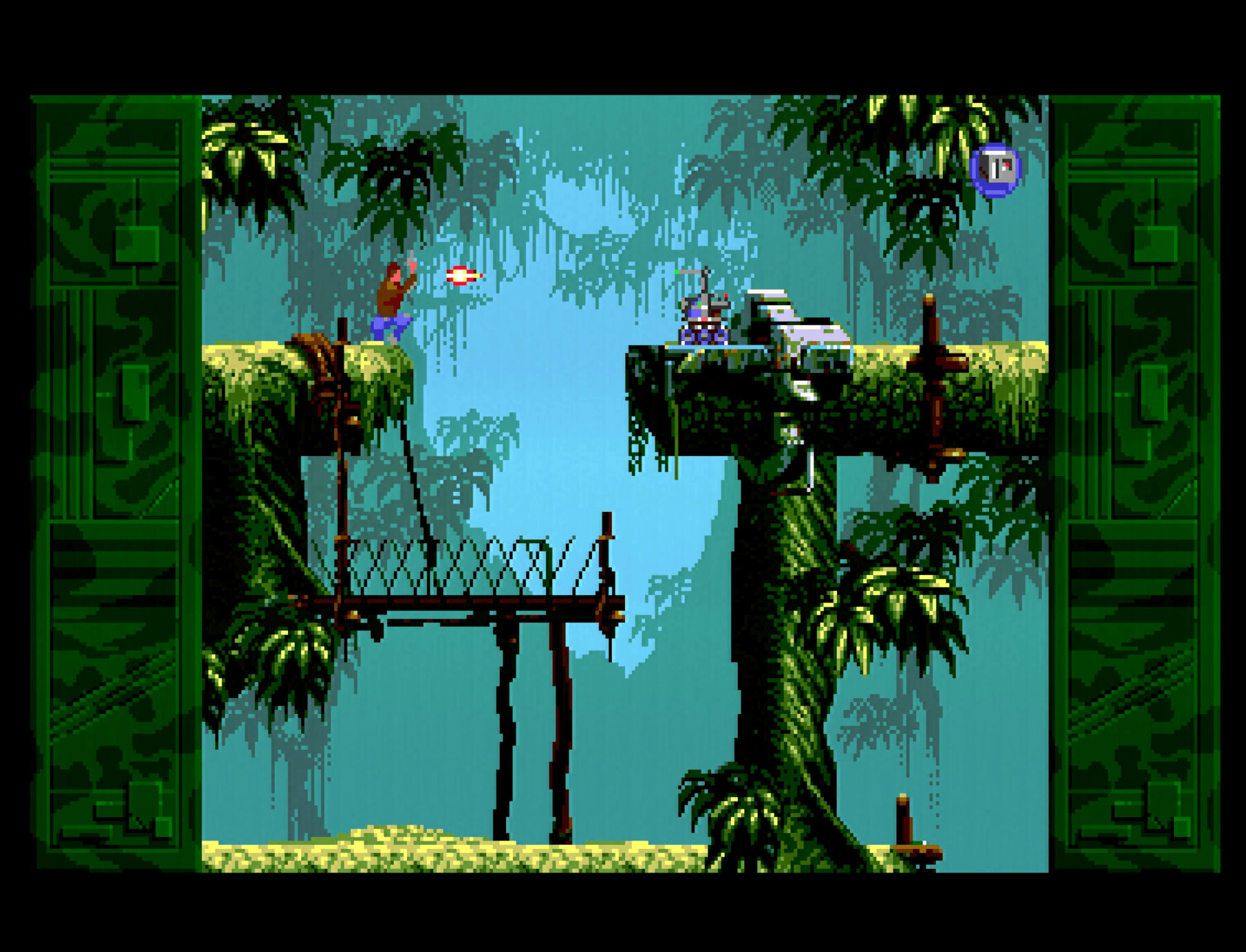
With all of that done I reassembled the system and setup on the bench for staging and then some captures on my RetroTink and Elgato4KX setup! You can see the captures below, I took them using a recently acquired Genesis 2 CSYNC FortraFlex cable. I have recently started acquiring batches of RetroAccess cables in FortraFlex as it’s the best feeling cable out there in terms of being flexible while also offering excellent shielding. Look for more captures with other cables coming in soon for the NeoGeo systems, PlayStation, etc.
Anyways… that’s another CDI done in 2026 and another order in the books!