When it comes to horrible RGB output / jailbars you see a lot of people talk about certain revision Genesis consoles (rightfully so) but rarely see any talk about the stock output from an SMS. I assume part of this is simply that not many people here in the USA care about the SMS as a console so it’s just overlooked but let me tell you… the jailbars you will find on one of these will make even your worst revision Genesis look pristine.
Luckily Zaxour has a kit that greatly improves/cleans up the output and the amount of SMS service requests I’ve seen thanks to that kit has really grown. There are still some faint traces of the jailbars even in the final image but it’s an incredible before and after and if you have one of these and plan on playing it via RGB on a scaler I would absolutely consider it a requirement. I have taken some 4K captures of the before and after and have shared them before (compare the left and right side of this image – https://x.com/RetroJeff83/status/1973380448769204331/photo/1 )
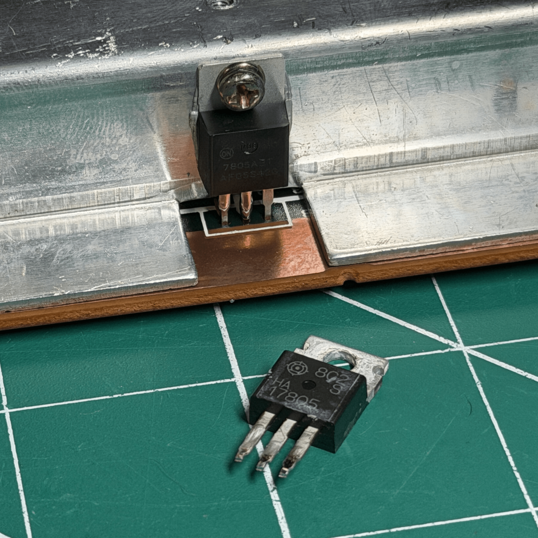
I wasn’t surprised to see another of these come in for all the usual work – Master Bypass, recap, cleaning and since you have to take the heatsink out and wire to the regulator anyways, a new 7805 voltage regulator. I have seen multiple SMS come back from the dead just by replacing that so I make it part of my regular maintenance on an SMS I touch (free of charge).
Read on for more details…
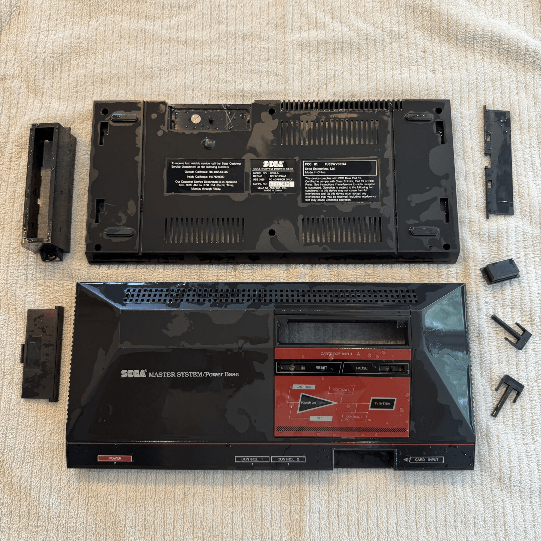
With the Full-Service Cleaning chosen I first disassembled the system entirely and removed all internals and separate the top shell parts including the pause and reset buttons and cart slot bracket/flap. All plastic parts were tossed in to soak, then washed and then set to dry overnight. Since water gets up into the light pipe area under the interface panel I proactively dry that area and extract any water that might not naturally evaporate next to my dehumidifier overnight to prevent the chance of any water droplets making their way down onto the board later during assembly.
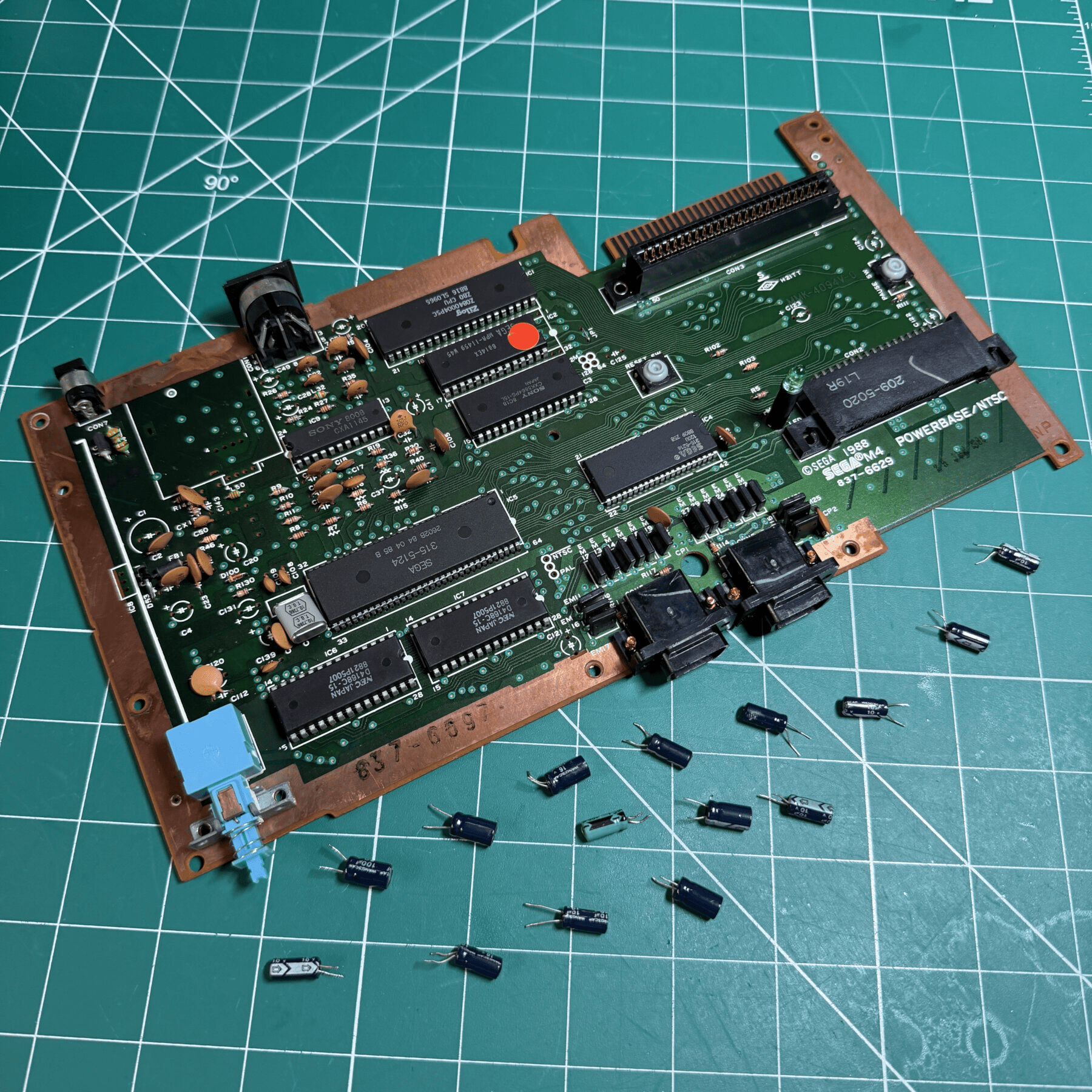
Once I had the mainboard extracted and top/bottom shields removed I detached the large heatsink and removed the voltage regulator so I had full access to the board and area I would be focusing most of my time on for the recap and Master Bypass install. I began by removing all the stock capacitors and during the process found about 6 or so cold solder joints in the area near the regulator so I reflowed any that were clearly cracked or looked suspicious and then cleaned the board thoroughly top and bottom.
With the clean board ready for new caps I installed them using a Console5 kit, minus C28 which would get removed during the Bypass install anyways and I left C27 lifted a little higher than normal as you have to use one of the legs as a tap point for audio. Much easier to think ahead like this then have to do more work later! With the recap out of the way, I temporarily screwed the heatsink back in so I could install the new regulator at the correct height and then removed, so now the new regulator is in place which is important for the next part of the job…

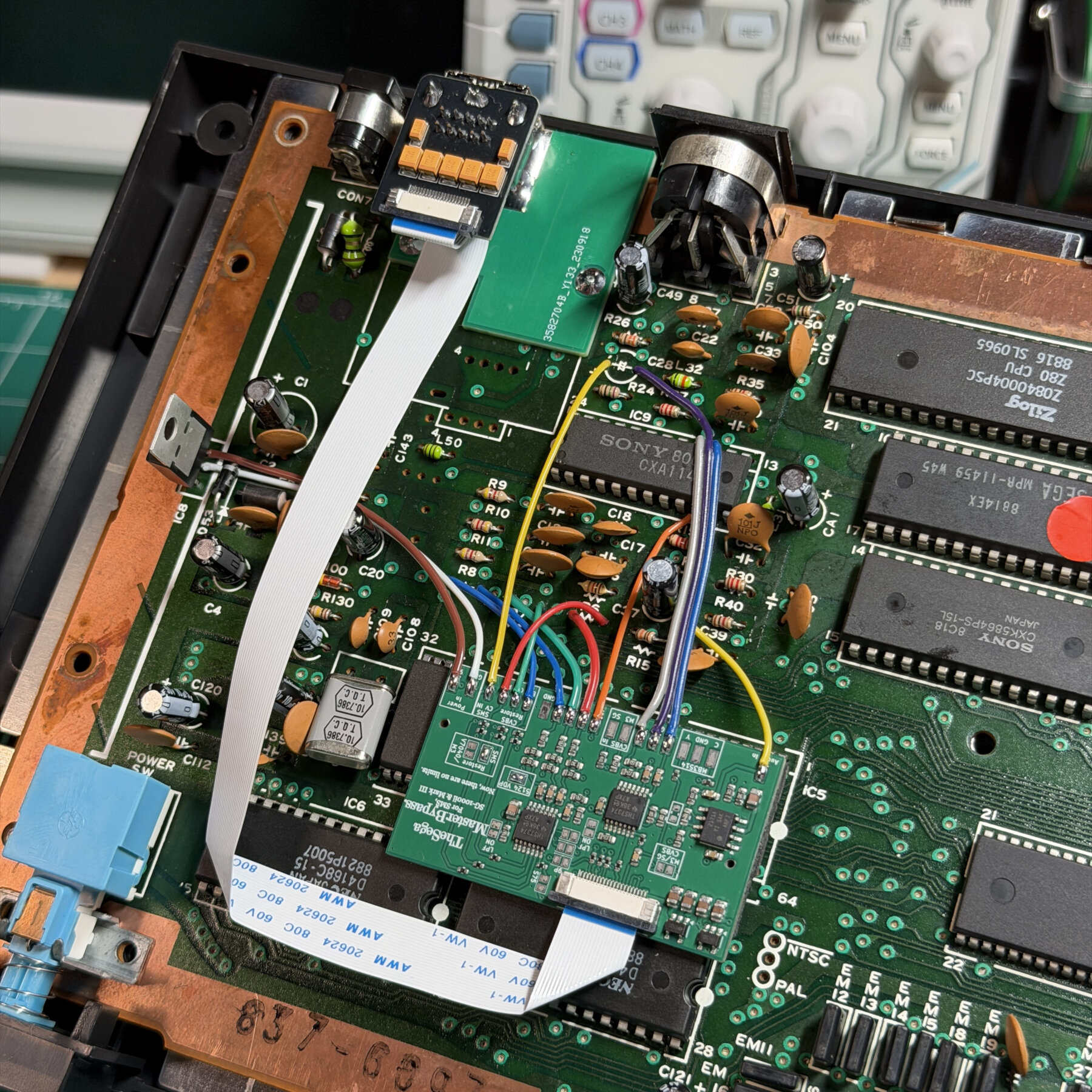
The Master bypass is a pretty easy install with the trickiest part IMO being the new 10-pin din mount. That’s because on many of the boards there are not plated through holes to securely solder the din bracket board and you definitely want a very solid install to avoid any risk of a customer inserting a cable too hard and breaking anything. In situations like this, Zaxour recommends using old component leads (I also have spare 26-gauge pins from old 3DO RGB mods that work) to solder to the underside then have it run through the old RF modulator holds and secure the top portion. This helps with horizontal pressure pushing into the console but you also don’t want the din trying to lift up when a cable is inserted either so just as important, I flood the area UNDER the din with solder and then aggressively lay a really thick fillet around all 3 sides and backfill a gap behind the DIN so it’s very secure to the board in towards the edge.
With that part out of the way (and I always take a spare 10 pin plug and insert/remove a few dozen times to work in the port a bit too, another Zaxour recommendation) I begin the breakout board install to the top of the din, mount the master bypass board to the 5124 chip and bridge the correct jumpers. Once all that is done it’s just a matter of connecting the RGB, sync, composite, svideo, 9v and ground points from various spots on the board. 9V and ground come from the regulator (which is why replacing BEFORE beginning this part is crucial) and the rest come from some removed resistors, the encoder chip or capacitor legs in the AV out area.
Because of all the various length runs and how scattered the points are keeping the wires in a tight bundle like on a Genesis Triple Bypass is really not feasible and its actually much easier and clean to just run separate wires.
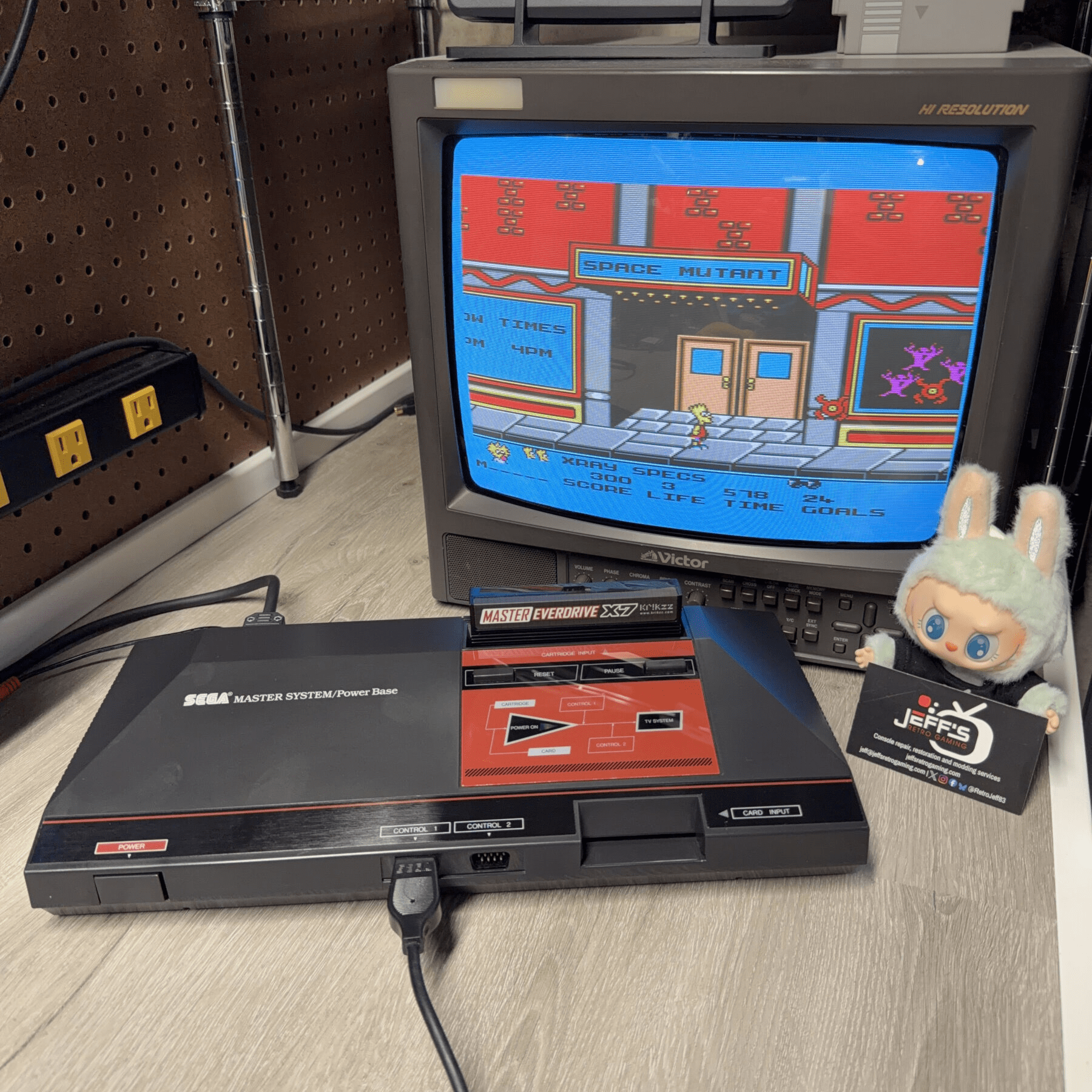
Once done, I fold the flex carefully, connect it and secure any slack with some double-sided tape. A quick power on test after securing the heatsink back to the regulator with some fresh thermal paste and also confirm video and audio out not just the new 10-pin din but also the stock AV out (which should still work) and I know I’m good to close this up and sign off on the sticker.
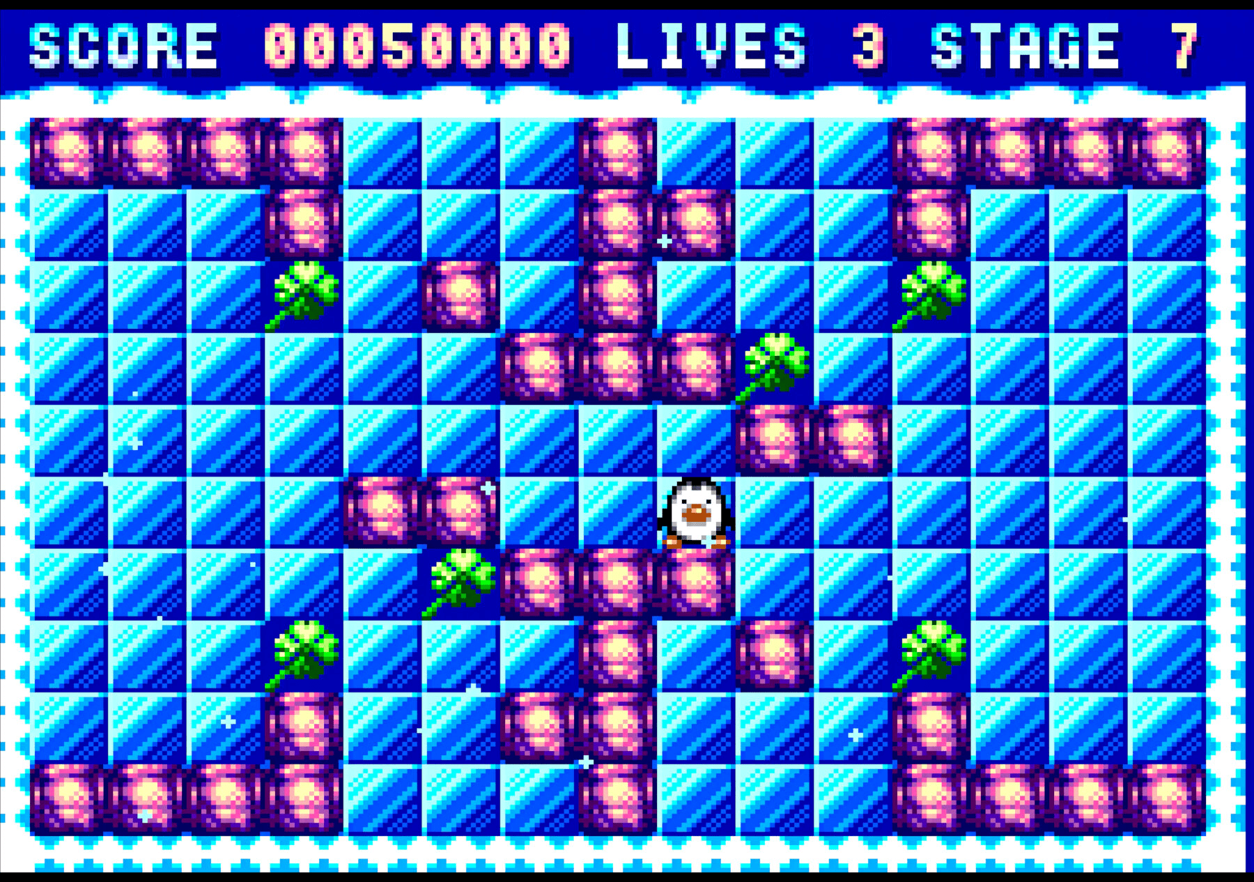
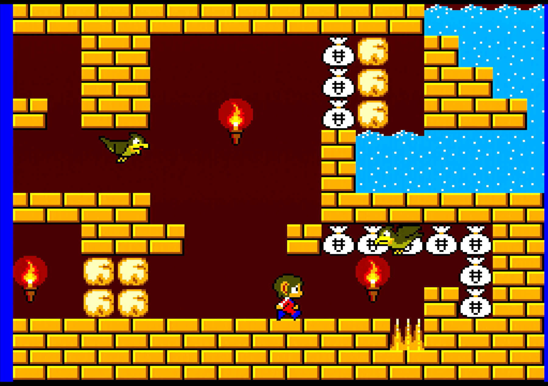
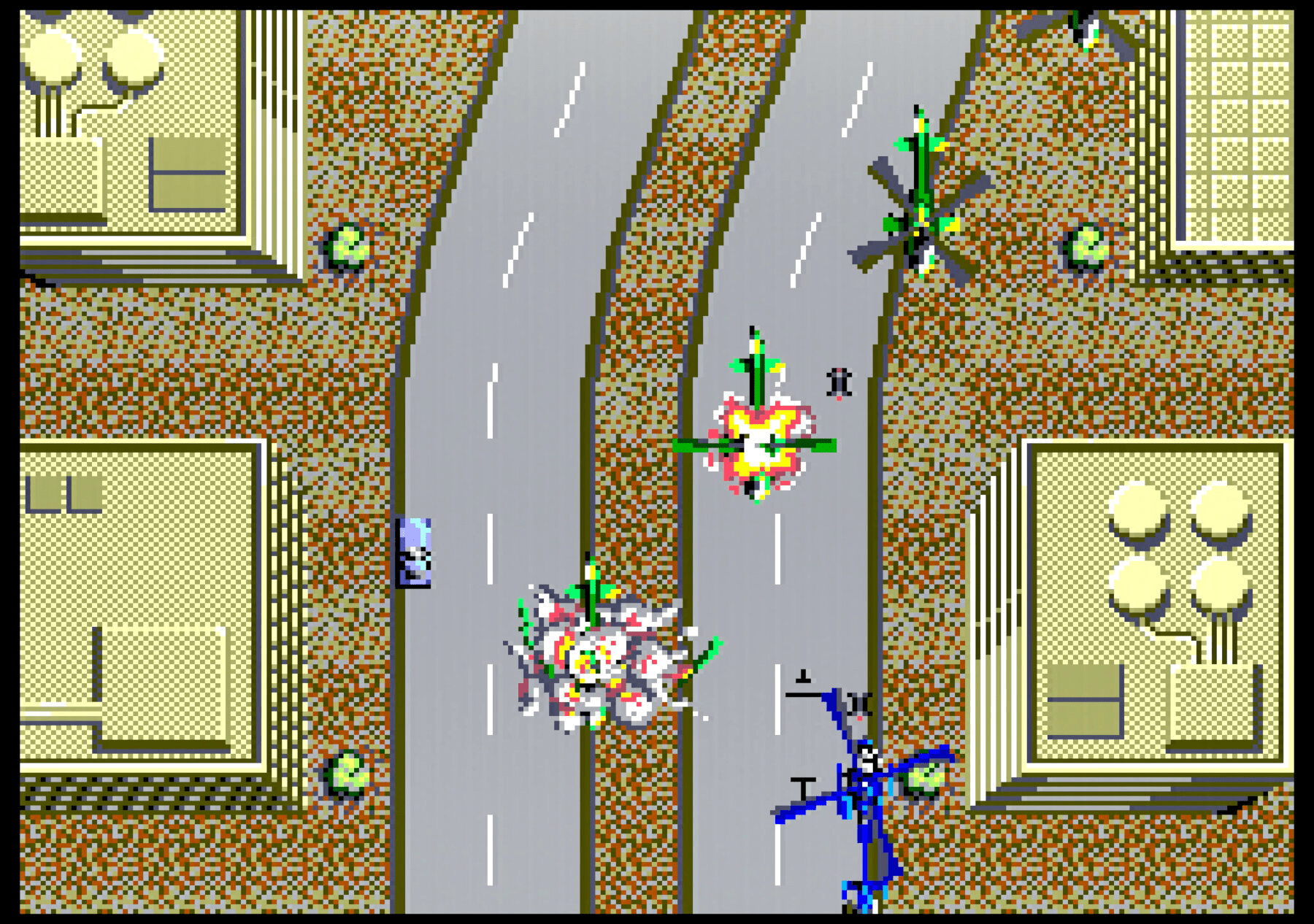
Gave it a few hours burn in time on the bench and played some games for capture, see the results below! You can still see traces of the bars in the solid color areas (gray and blue are most prone) but again compared to before it’s a huge upgrade.
Another SMS and order in the books!