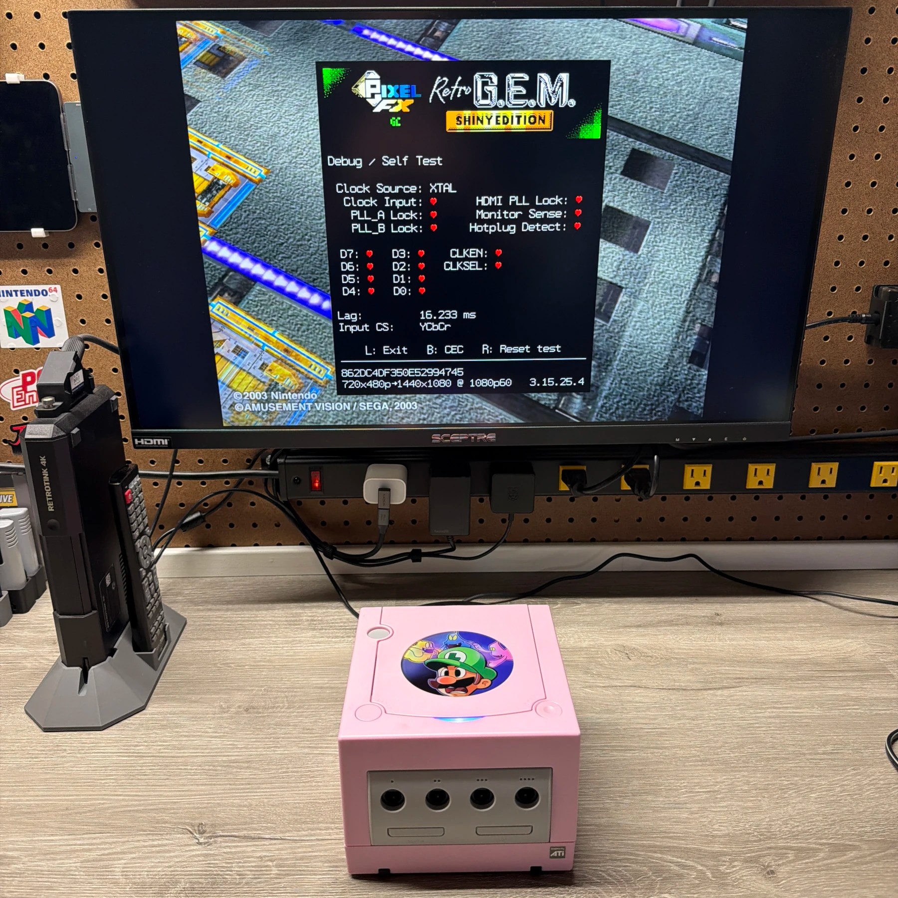
Console #2 I wanted to put together for the Retro World Expo was this custom GameCube! I actually have multiple units in various states of needing refurbishment but this one specifically was re-homed from an indigo shell that had cracks and chips and sun fading beyond what would be reasonably restorable so it was the perfect candidate for an aftermarket shell.
I grabbed this cute pink one from GamerGhosts shop a while back and had since acquired some decals from him to go with it and besides having to acquire a PixelFX Shiny kit, all the other parts were already on hand including the Pico chip, cap kit, battery, etc. Even though the shell came with an original style jewel I had seen some custom ones for sale on RockerGamings website so I decided to pick one that I thought kind of matched the shell well and loved the look of this Luigi’s Mansion one. Lastly I grabbed an SD2SP2 pro adapter from LaserBear since he prints colors that could kind of match the pink and its the most secure and reliable SP2 adapter you can find. Many of the cheap ones floating around on AliExpress and Amazon have thin gold fingers that can easily slide out and cause boot issues.
Follow along for the work that went into this one…
The first step before completely tearing down the original GameCube was to check operation as I had not done this since acquiring the lot some time ago. It booted right up, asked for date/time (not surprised) but output a video signal and audio on both its analog and digital ports. It would not boot a disc but I let it run for a while and then tried again and it did but struggled, in my experience the telltale sign of bad caps on the optical drive board which is the cause of no disc reading on most GameCube’s.
With some testing done I then completely tore down the original system and set each part into groups to tackle one at a time and then discarded the bad shell pieces. I was able to salvage the handle, original jewel, light pipe and other various accessories which will go into storage for good spares since the new shell came with all the parts even the memory card flap springs. Sadly, the main top and bottom shell and lid are just too far gone so those got tossed completely.
I then wiped down and cleaned the metal brackets and shielding that goes underneath the mainboard and assembled the new shell up to the point where I would install the mainboard. The plan was to refurbish/mod and build my way up from bottom to top and assemble as I moved along. With the job now ready for the mainboard which is where 99% of the work would be taking place, it was time to prep and refurbish the board before both primary mods were installed.
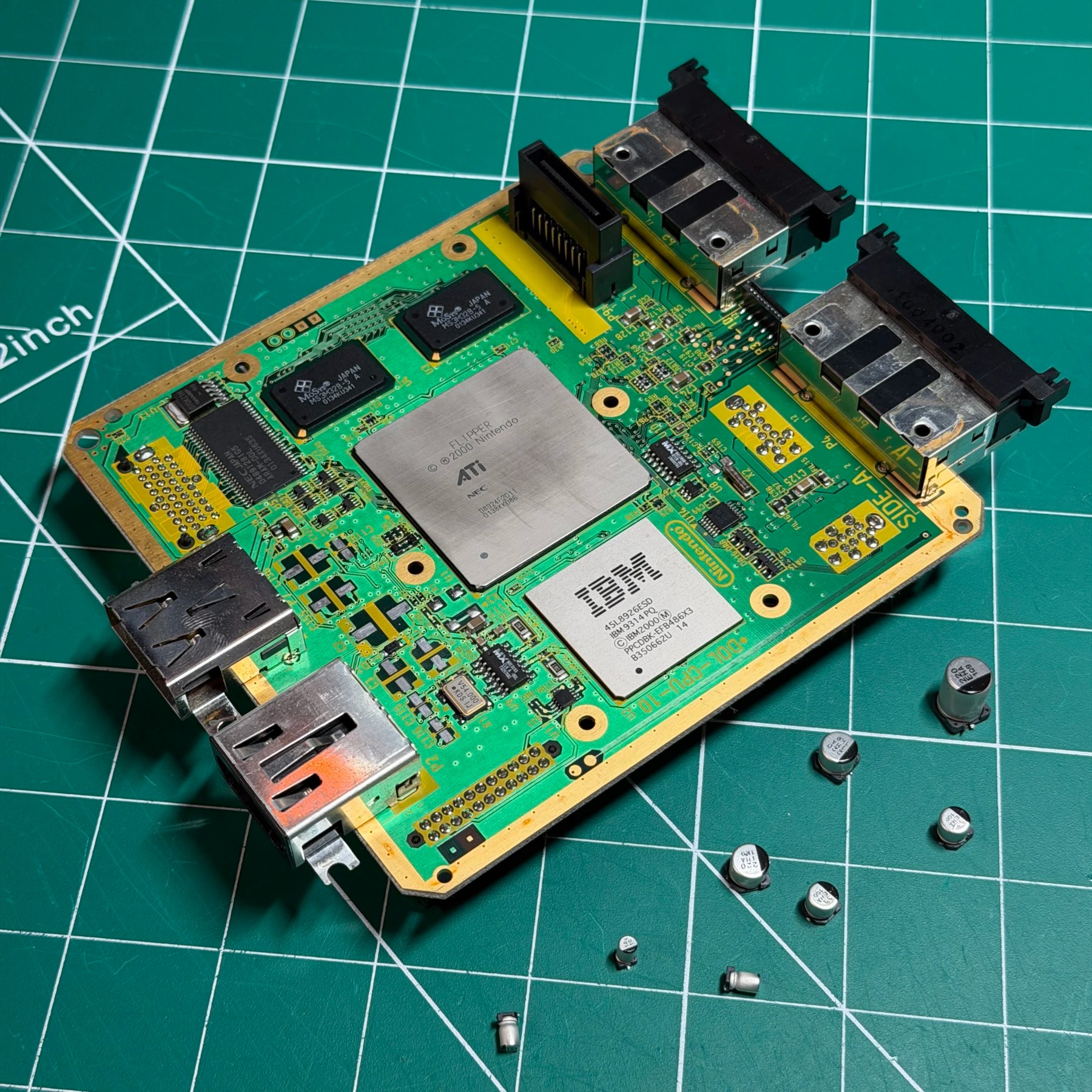
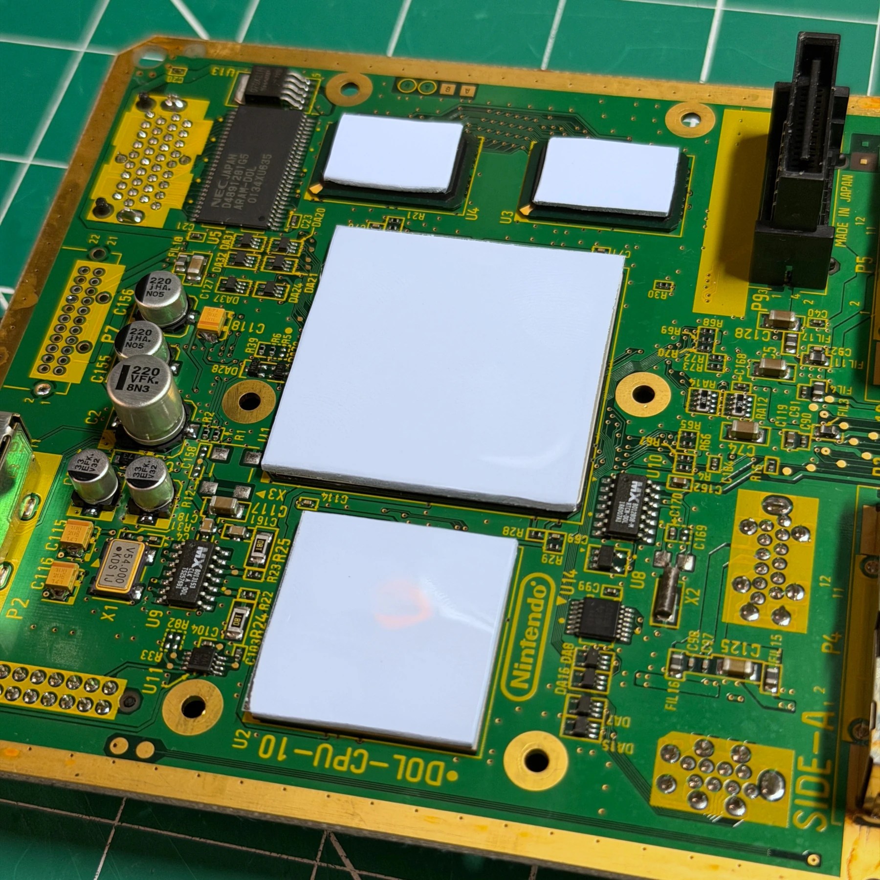
Step 1 was to remove the heatsink and clean that, then set aside and remove the stock capacitors with my hot tweezers. Once those were removed and pads cleared I cleaned the board top and bottom thoroughly then soldered on all new electrolytics from Console5! Next I grabbed my handy GamerGhosts thermal pad templates and cut new pads and secured to the top of the CPU/GPU/RAM chips. With the refurbishment done it was time to start on the HDMI and Pico mods but I kept the heatsink off for now so I still had easy access to wire up the Pico…
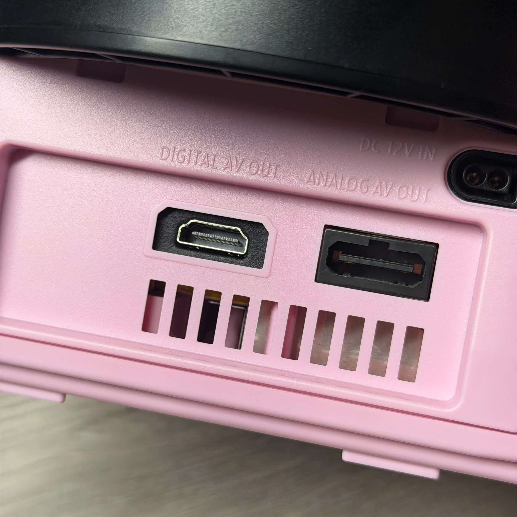
…but first lets get that PixelFX kit done! The GameCube version of the RetroGEM is one of the easier ones to install IMO only a tad bit tougher than the Nintendo 64. The first step is to choose what port you want to sacrifice and remove it, unless you are doing a cut method (or 3D printing a new bracket with the HDMI cutout above). I prefer injection molded rear plates and not having to do cuts and since this is a DOL-001 with both digital and analog, I always sacrifice digital unless a customer requests otherwise. This is because there are no good cables to utilize the digital out port except OEM and those are super expensive and rare. There is the Carby which is great but that just gets you HDMI which this mod does and much better so… not much use for a digital out port at this point. The analog does still have value though as it gives you flexibility to move between the HD setup and a CRT TV if you have one that can take composite and s-video which is the best an NTSC GameCube can do anyways!
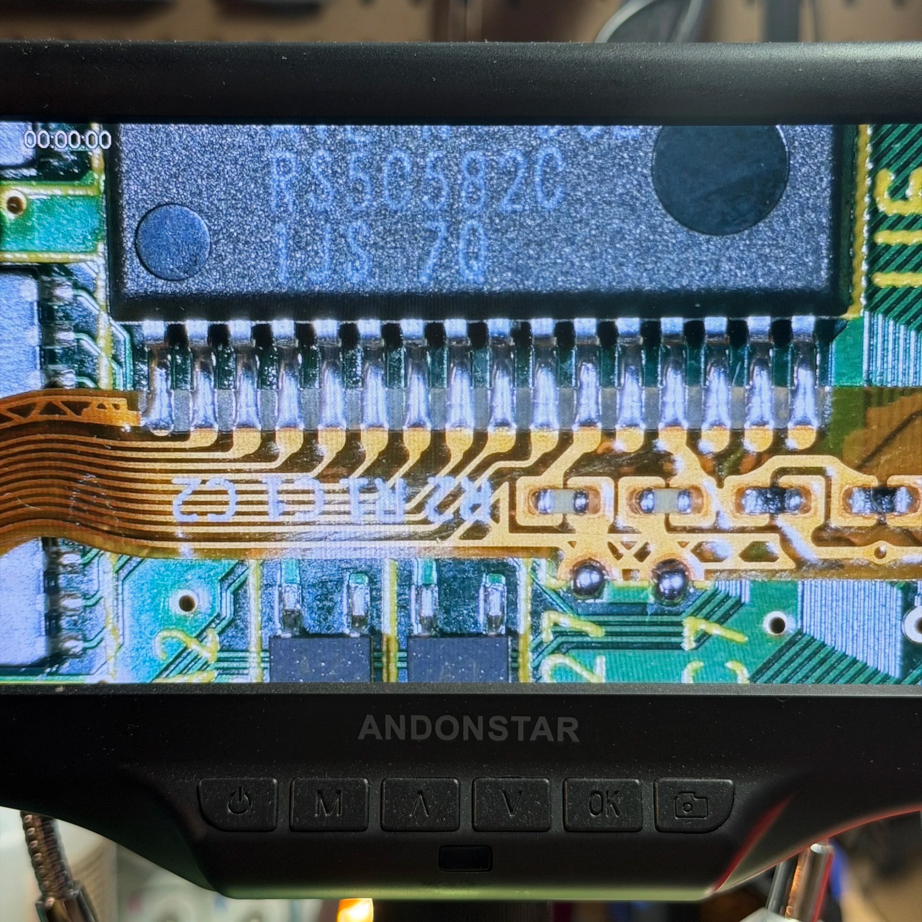
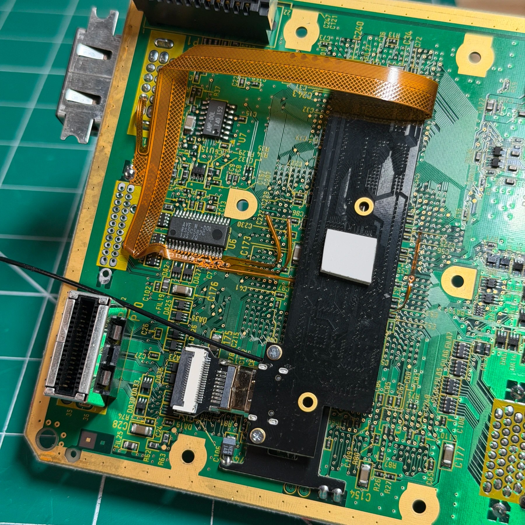
I set the jumpers on the GEM board, soldered the support bracket to the underside and then prepped the flex solder points. You have to scrape 2 spots near the AVE chip which are used as anchors and then 4 coated vias in the center where the flex arms will attach. The AVE chip is not super fine pitched or large so it’s not too tough, I like to bring in my knife tip in and anchor the right side which sits completely flat, then push in the left side (the flex rides on top of a nearby component) with some tweezers and tack that point down. Once I do that and check alignment I bring in a bunch of flux and carefully drag solder up and down the pins 3 or 4 times to ensure nice even smooth joints on all the pins and then also solder those 2 anchor points. With that done you just need to bring the 4 arms over to the exposed vias and solder them on paying attention to which one goes where and most importantly being gentle with them… you don’t want to damage the trace running up those thin flex arms!
Once those 4 points are soldered it’s just a matter of bending the flex 90 degrees and soldering to 5V and GND on the rear ports. You then make another 90-degree bend and connect to the GEM board and attach the HDMI flex adapter and Wi-Fi antenna before screwing into the previously soldered on support posts. With a small thermal pad attached to the GEM chip the HDMI mod is now done besides the actual port but that will come later, so on to the Pico next.
I chose the Picoboot option for this premod as its much more cost effective than something like the GCLoader and you get to retain the optical disc drive which I knew a recap would fix. Picoloader mods are great but the kits are pricier and it offers no benefits unless you are someone who cannot solder and want the plug-and-play installation. With a proper install and good SD card adapter the Picoboot is a tried-and-true option for any GameCube.
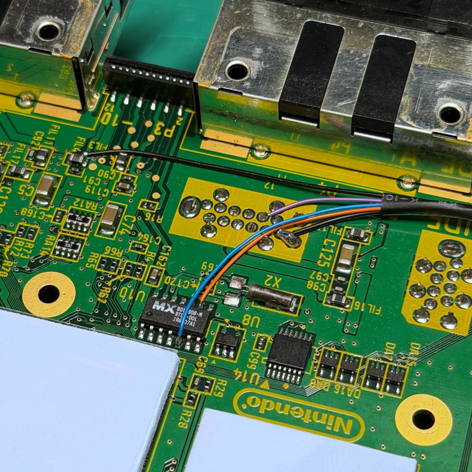
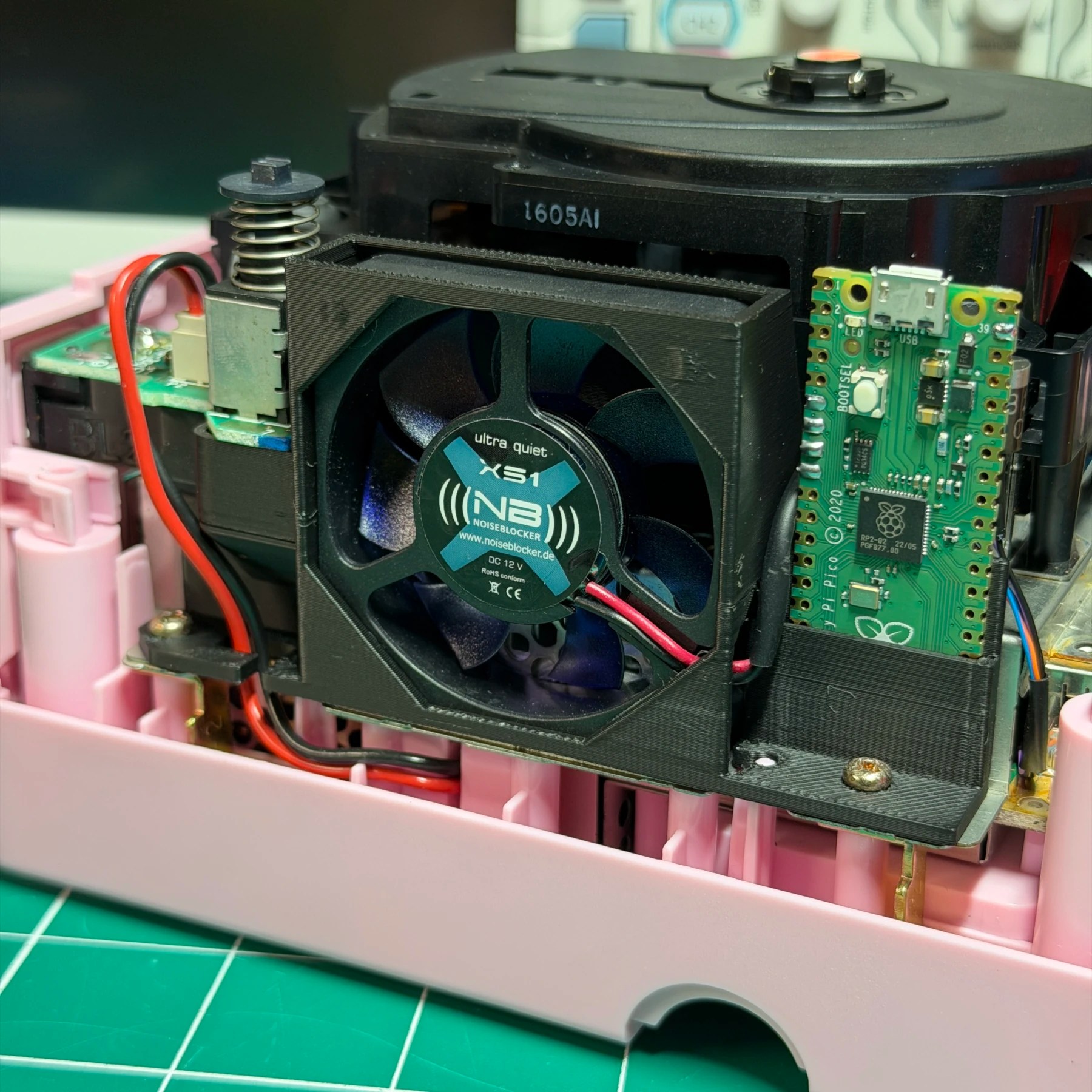
The key to a reliable and stable Picoboot install is to use the shortest wires possible so this involves smart routing and placement of the Pico chip itself. I prefer to route my wires out the front left corner then mount the Pico in a 3D printed bracket either standalone or combined with a fan upgrade (like in this case) next to the fan on the left side of the GameCube.
Any modern install should use the 5V VSYS method so I connect my larger 26awg wires to that and GND then my 30awg to the other 3 data points and carefully bundle them together in some heat shrink and run towards the corner of the board. Overall its a very easy install on the mainboard side and now that the wiring is done and HDMI mod done on the underside I can wrap it up on the mainboard so I remove the plastic sheets from the thermal pads and place the cleaned heatsink on top. At this point the board is install-ready so I screw it into the lower shell and it’s time to move on to the optical drive!
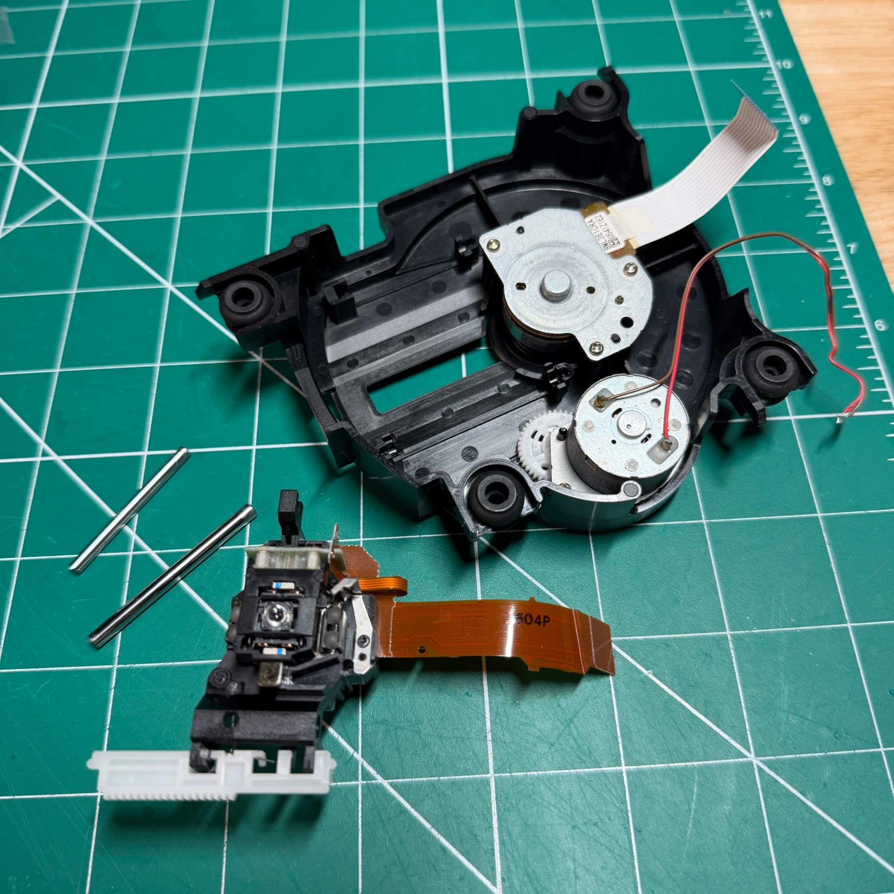
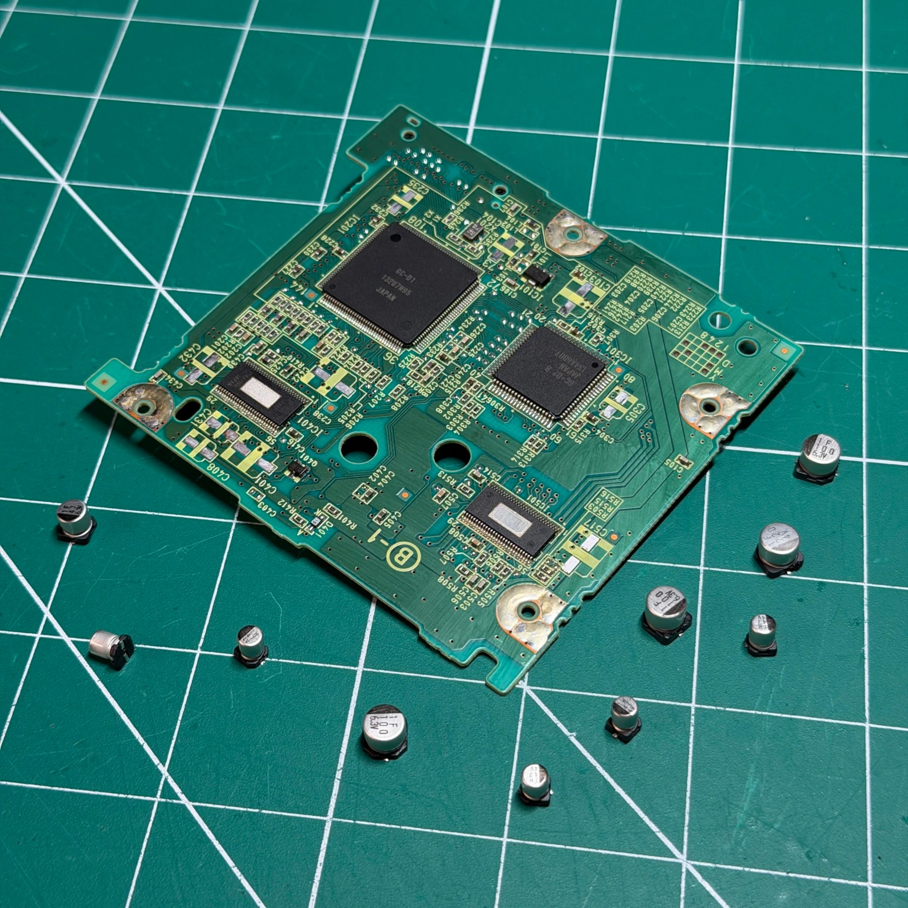
Once the optical drive is removed from the upper shielding I go through the process of removing the wires, flexes and connectors to separate the optical drive PCB from the laser assembly itself. After its separated, I use my hot tweezers to quickly remove the 10 electrolytic caps and clean the pads and board. Once cleaned, I add flux and solder on the new caps from the Console5 kit and clean up any unspent flux so now the PCB is done. For the drive cleaning I further separate th assembly from the plastic base, clean the base and then unscrew both rails and remove the laser so that both rails, the gears and the teeth can be cleaned and greased appropriately.
While its apart I will carefully clean the lens and manually move the laser up and down the rails to spread out and work the new grease in. With that done and the drive all re-assembled I clean the top shield and then re-attach the drive assembly to the top shield so it can be placed down on top of the mainboard/heatsink.
With that top shield reinstalled and the HDMI mod flex carefully routed out the now vacant digital port spot and the Pico wires out the front left corner, I can begin working on the last few pieces before final assembly. Next up is the fan and Pico mount which I 3D printed and houses both of those plus the PSU connector. Noiseblocker fans can interface directly with the stock GameCube fan connector you just need to cut that off the stock fan, cut the noiseblocker wires and splice them together. I do this with the fan secured into the mount so I can do a nice tight run with no slack and also use heat shrink over the joints. I also remove the sticker and desolder the white wire completely as its not needed at all. The fan should otherwise snap right in place no screws so once that’s done, time to get the Pico chip wired up.
Just like with the fan I like my wires as clean as possible so I push the modchip down into the 3D printed socket and then pull each wire up and route to its corresponding pad so I can mark/strip/tin and then solder in place without having any extra unneeded length. The only thing I do before is install the diode in place for the Vsys pin. I used to just have the diode in-line buy they are quite large so what I find works best is to bend the striped side lead and cut flush then solder that directly to the Pico chip pin as the pad is large and a with a nice solid joint its very sturdy. I then solder the vsys wire to the other side and put more heatshrink on the connection. The rest of the wires are fed stripped end through the hole and then bent at 90 degrees and soldered on the front side of the pad for a clean install 👍
With the fan, PSU connector and now Pico chip all installed and secured to the mount and the top shield screwed down, all that’s left is the controller board work and reassembling the top shell.
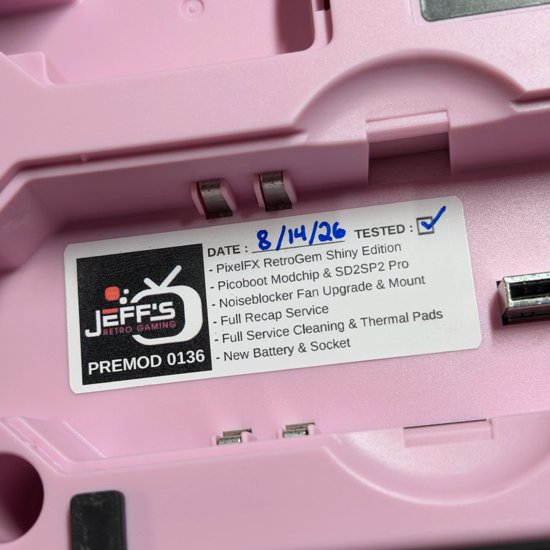
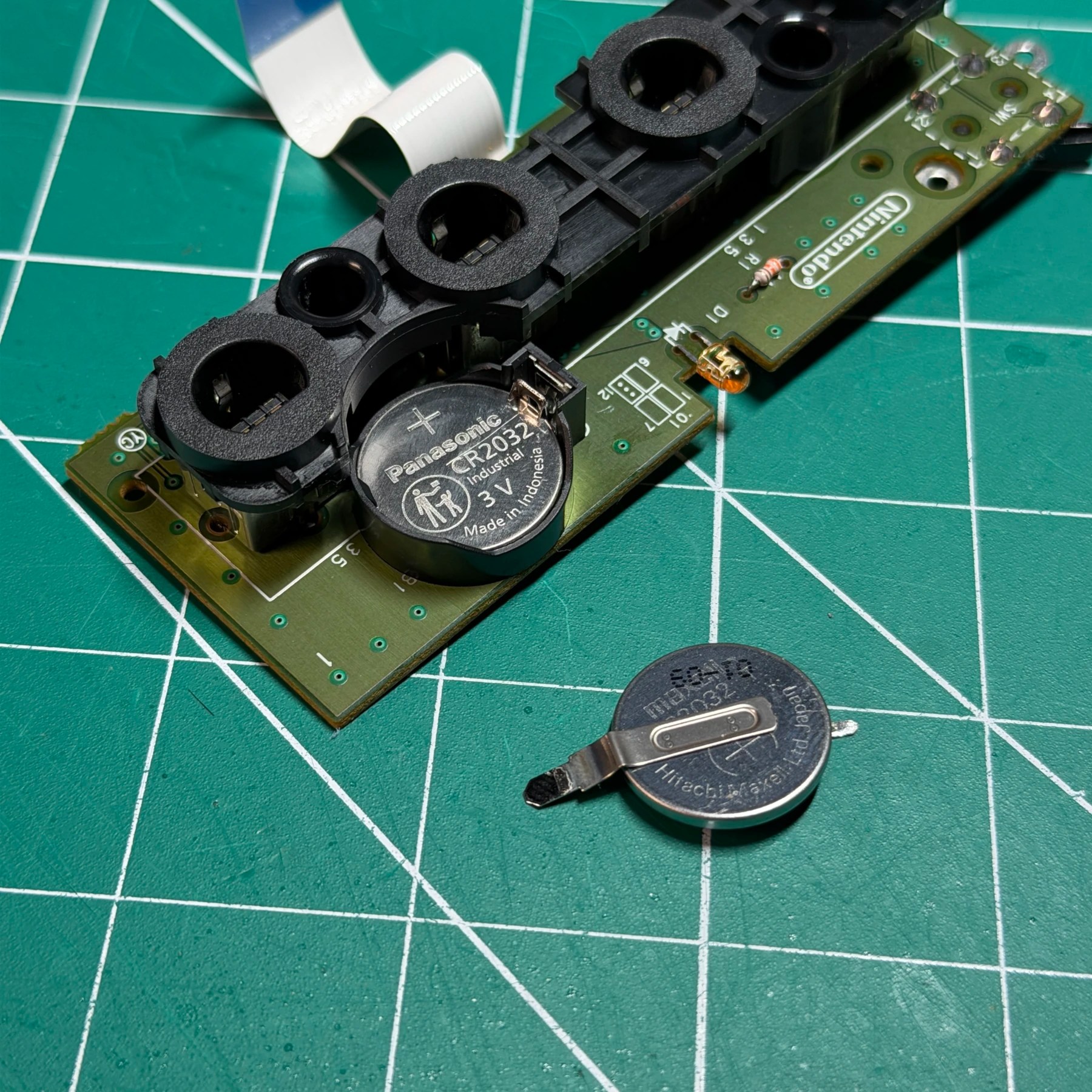
For the controller board all we need to do is remove the old CR2032, install a socket and then snap in a fresh battery. This process is super easy and will prevent the owner from getting nagged about date/time on boot and allow easy future swaps with no soldering! Normally I dont touch the LED on these but for this build the orange and pink just didnt go together quite well so I tested a white, green and blue LED and settled on the latter as the best fit which matched the jewel a bit and looks quite sharp!
I unpackaged the new shell memory card flaps and springs and got those seated, then installed the controller board into the new faceplate. Top shell assembly was easy with the handle and light pipe, fan vent grille and all other parts fitting together just like a stock shell. The new HDMI port bracket gets screwed into place on the back where the digital out port used to be and I tested alignment with the rear plate before committing the rest of the screws and shell. On the jewel front this aftermarket one doesn’t come with the plastic retention clips but instead a large super sticky sheet on the bottom so I carefully taped and marked the top center and got it aligned well and then pushed it into place. Before actually installing the top shell I wanted to test everything including HDMI output, analog output, ODE operation etc. and make sure the new thermal pads were transferring heat and fan moving it out of the shell properly.
At first boot the HDMI signal came right through on my capture setup and I was able to bring up the PixelFX menu to check the health/debug and all hearts so all connections are good! I then joined wifi and updated firmware to latest stable release and changed output to 1080P from the default 720P. Swiss was launching from the SD card perfectly and my 4 test games I loaded up all patched and launched great so I configured SWISS and even though I can’t provide games with the system it will come with a small 64gb card with the DOL file and configured settings for whoever buys it so they only need to add games to the root and they will be good to go!
After several hours of playback and testing the unit was running perfectly, nice and quiet and looking razor sharp. Another GameCube in the books and this one will be making its way to the expo for sale in less than a month! If for some reason I end up unable to make it to the show or it doesnt sell there, keep your eyes out here as it will then be listed in the Pre-Modded section for sure – https://jeffsretrogaming.com/pre-modded-systems/