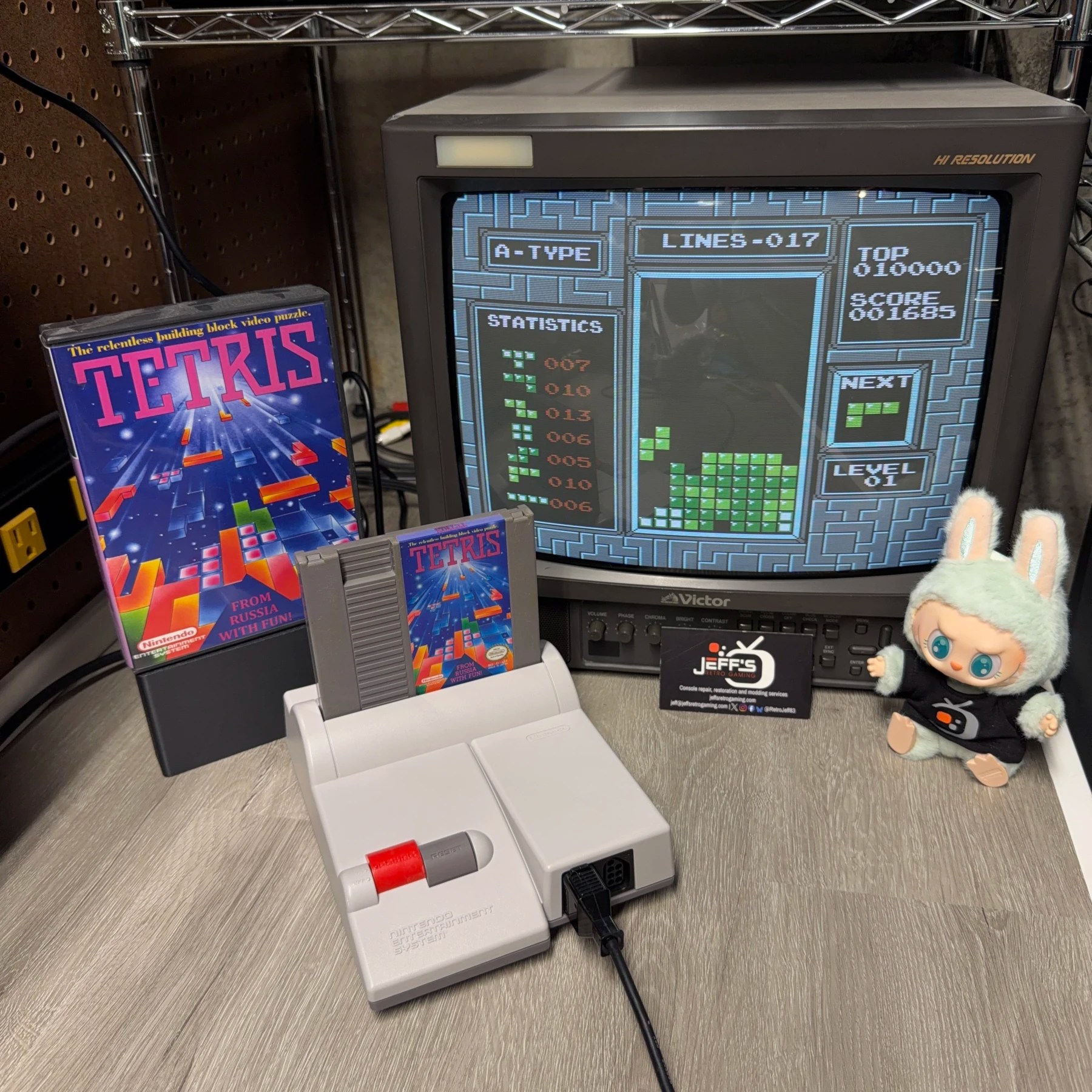
This was the second request for the newer NESRGB V5 kit to be installed, this time in a Toploader model (previous install was on a Frontloader, seen here – https://jeffsretrogaming.com/blog-co-9921/)
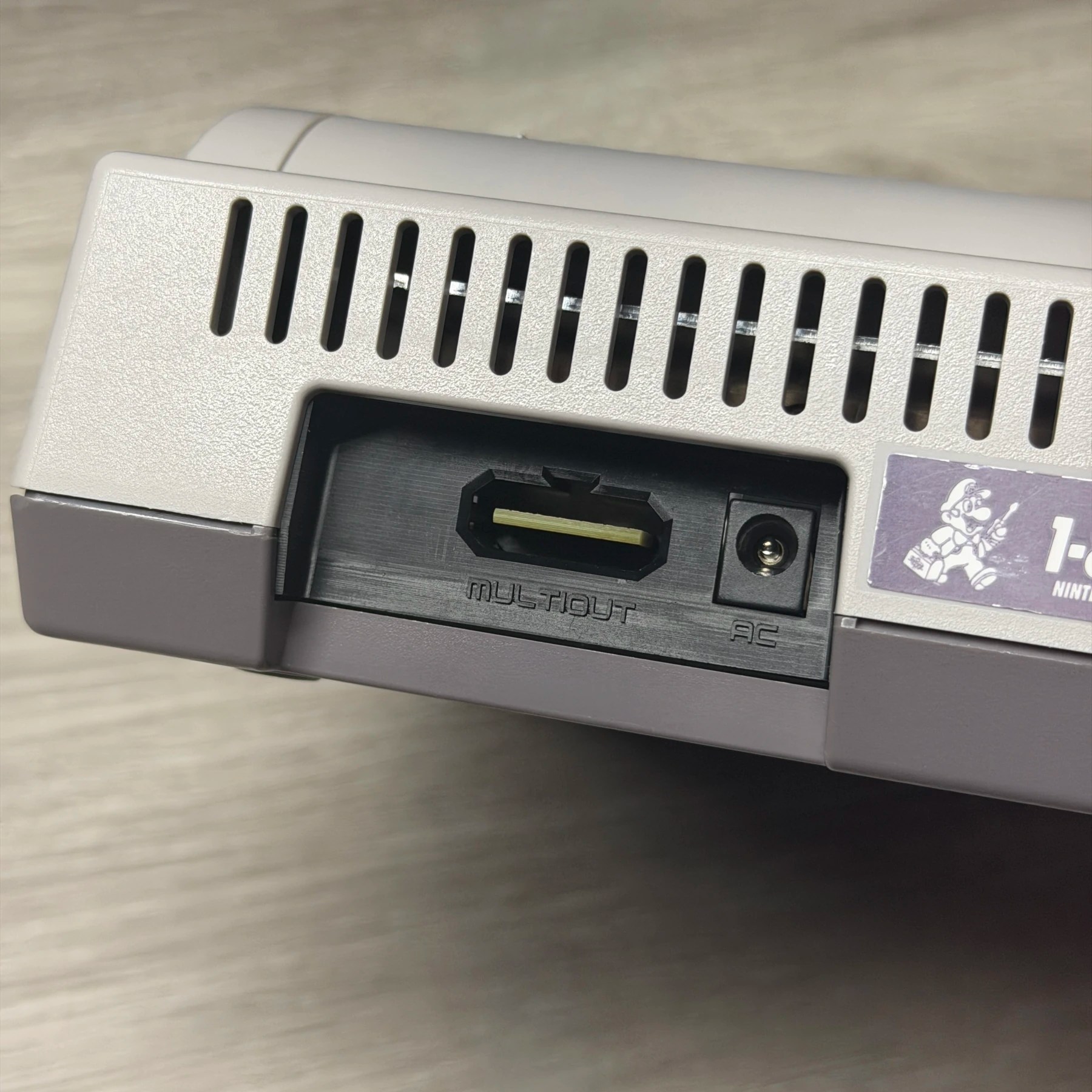
They had also requested a Full-Service Cleaning and Full Recap Service and provided the correct LaserBear multiout panel (Seriously, sounds like a minor detail but I get sent incorrect parts ALL the time so this always makes my day 🙏) so knowing all that it should be a straightforward and relatively easy job!
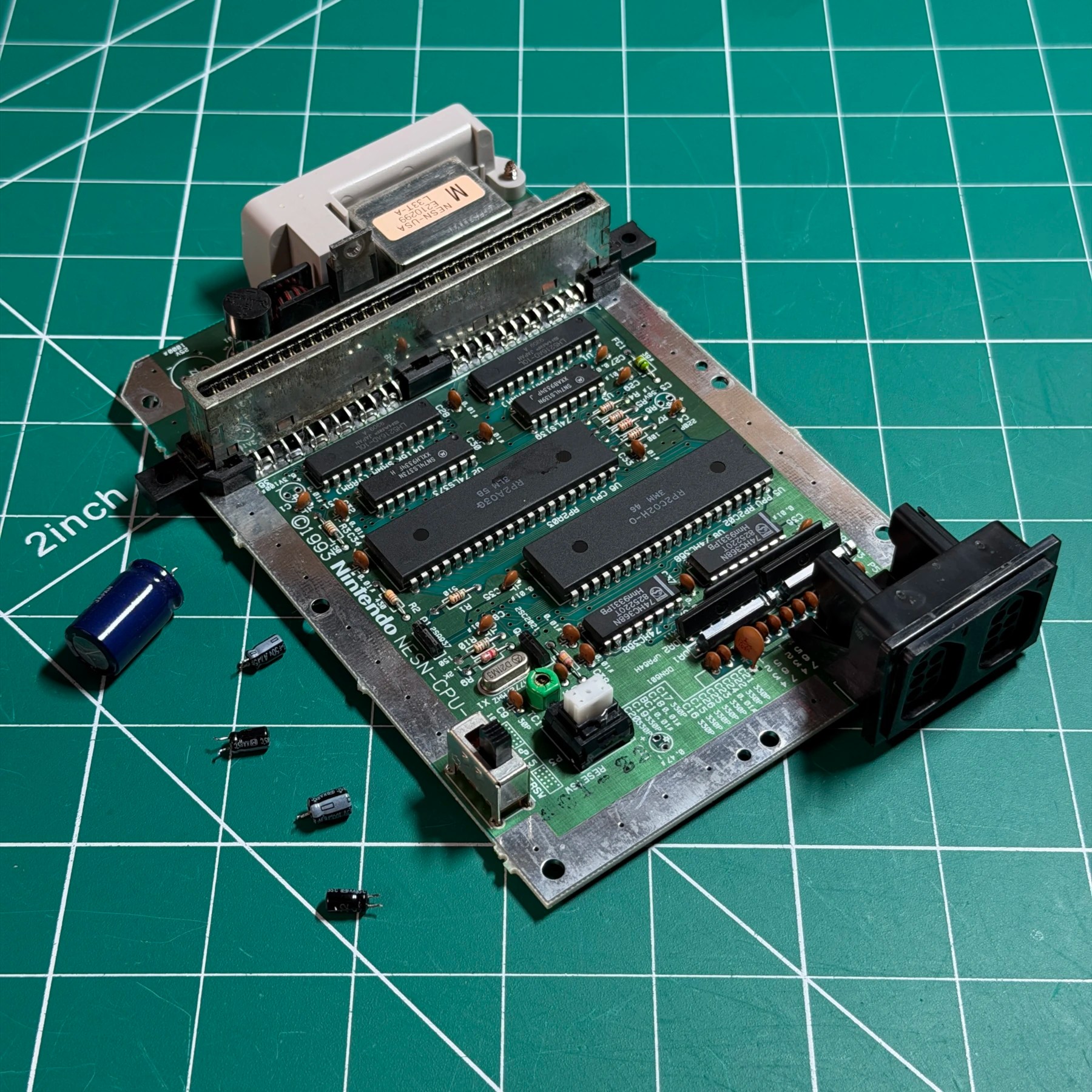
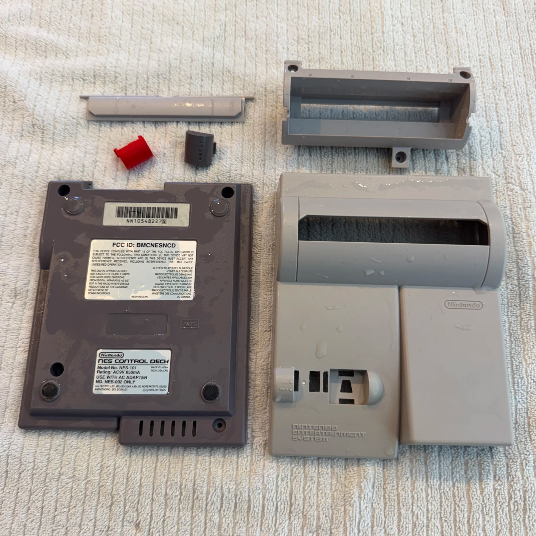
Got to work straight away by disassembling the top and bottom shell and separating out the reset/power button and cart slot bracket to all be cleaned. All plastic components were then soaked, scrubbed and washed and set to dry overnight. As those parts were drying I quickly removed the 5 electrolytic capacitors to be replaced then cleaned the board top and bottom side thoroughly before soldering in the new replacements from Console5!
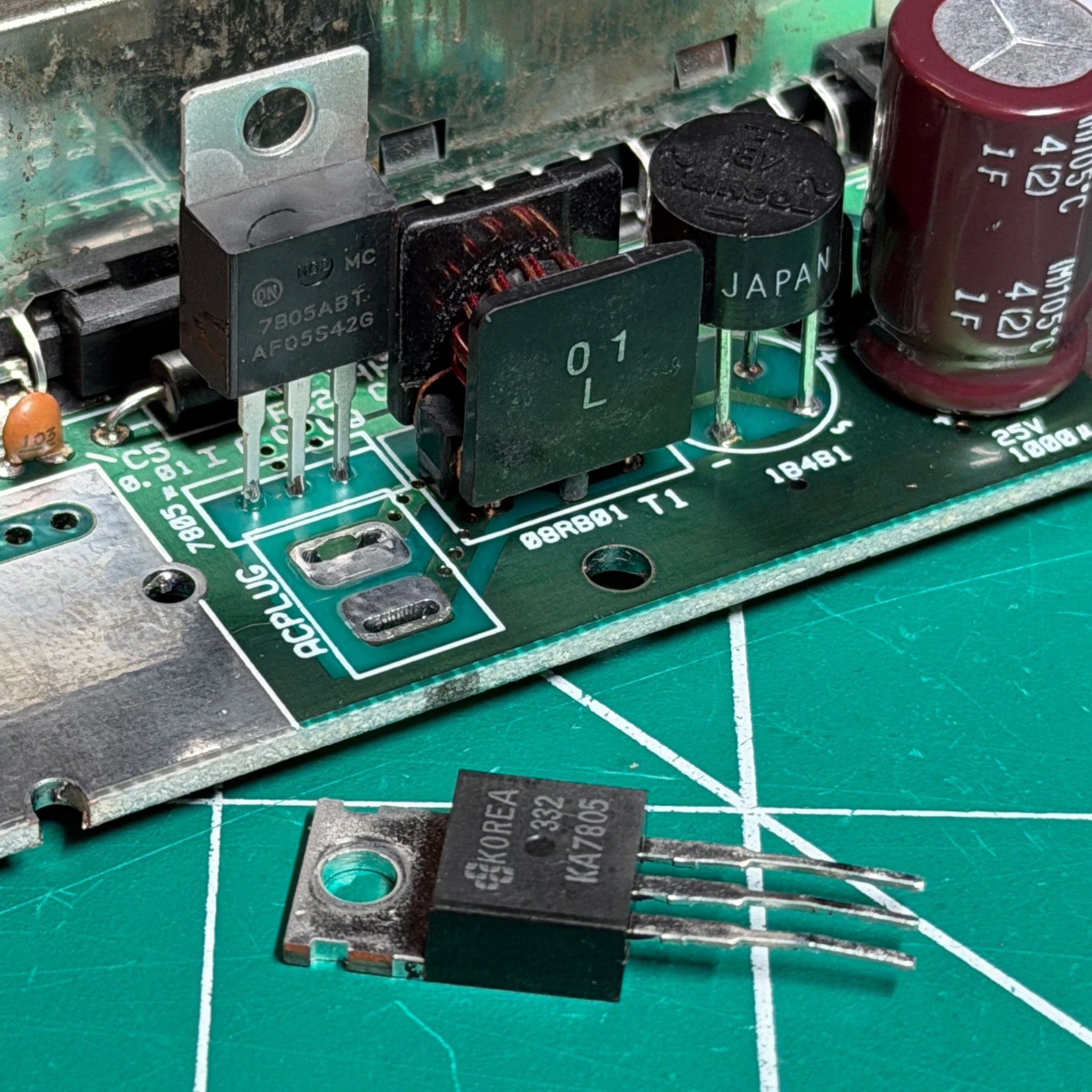
With the cleaning and recap done I then started on prepping a few more board areas for the upcoming NESRGB part of the job including desoldering the original RF modulator, remove the screws holding the stock rear panel and desoldered the AC power jack (which gets replaced in the kit). Lastly since the heatsink had to come out for cleaning and access to the rear panel I removed the voltage regulator and set to the side for now.
The two biggest parts of a NESRGB install are the PPU pull and the board assembly/wiring. For the PPU pull I always introduce a good amount of fresh solder to the PPU pins so that when I clear the holes with my Hakko gun I’m much less likely to have any remaining old solder stuck to the pins. With a nice cleared out gun I work my way from pin 1 around clockwise to pin 40 and I’m able to have the chip practically fall out when turning the board over. At most I sometimes need to gently pry under the chip with a plastic spudger if the pins are bent out a tiny bit but there should be little resistance… If there is use tweezers to try and wiggle and check the pins and you likely have some leftover solder holding one in place.
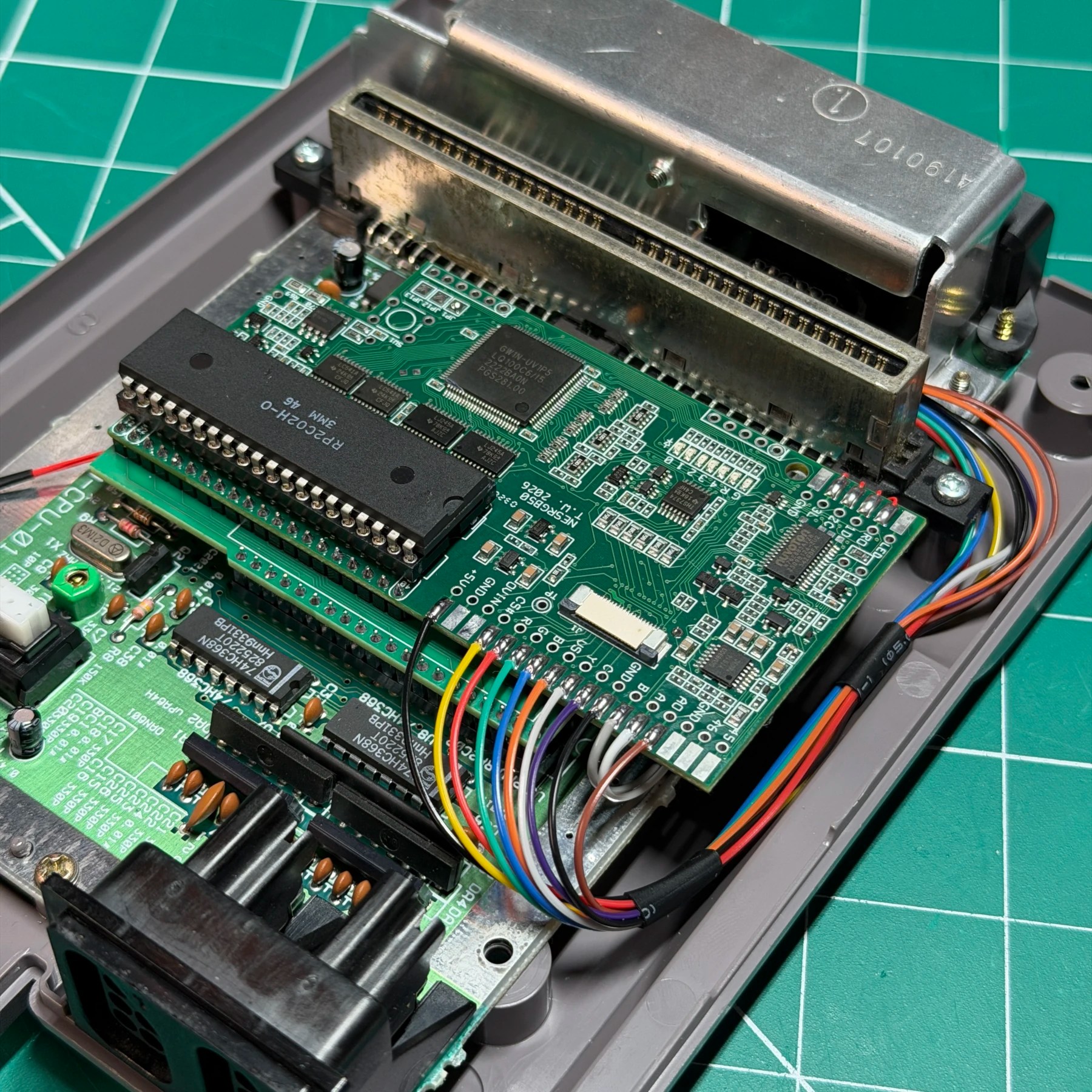
With the PPU cleanly pulled it’s just a matter of following the instructions and soldering in the 40-pin socket, pin headers to the adapter board, then the NESRGB board, the second 40-pin socket, etc. Not difficult but a decent amount of soldering as you are accounting for the 40 pins of the PPU 3 times! Before socketing the NESRGB onto the mainboard though its best to wire up Audio A & B to CPU Pins 1 & 2 as it will be substantially more difficult to do so once that board is in the way.
Once the board is fully assembled and socketed there is only one single jumper to set (JP1) and that’s it, much less compared to earlier versions. Now it’s time for the wiring…
Since the customer wants a SNES style multiout installed and there are enough pins to allow for the use of RGB, S-Video AND composite there is no reason not to wire them all up so the customer has ultimate flexibility going forward. I tin all the relevant pads also including GND and Audio and 5V and start separating, stripping and tinning all the wires I will need (I use 28awg stranded).
I first bend and mark and cut/strip/tin the 2 aforementioned audio wires onto the NESRGB and then start soldering the rest onto the NESRGB pads working from the inside to the outside. With all the wires in place I then take them one at a time, from inside to out and route along the path to the side and including both bends where it will end up in the new multiout and mark for length cut. I do this for all wires at once, then cut/strip/tin the multiout end and solder all points onto the port using the LaserBear pinout map available on his website.
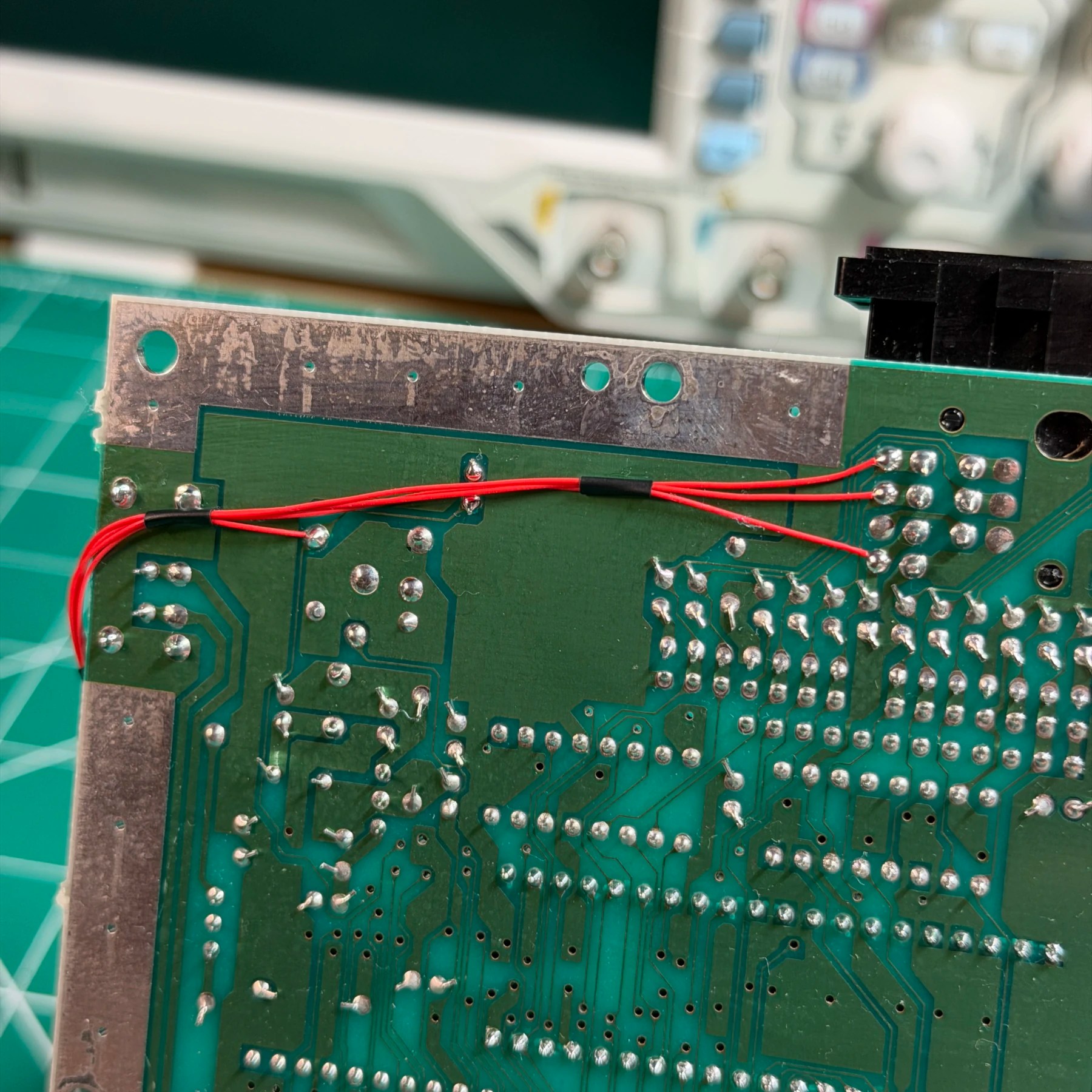
I then secure the bundle and multiout with kapton tape as I have work to do on the underside of the board once I solder 4 30awg Kynar wires to the controller/IGR pads on the opposite side of the NESRGB. With these attached then cleaned and bundled with some heat shrink tubing I route them carefully under the NESRGB and around the board via the left side. These all get soldered to points for data, latch, clock and reset near the front of the PCB.
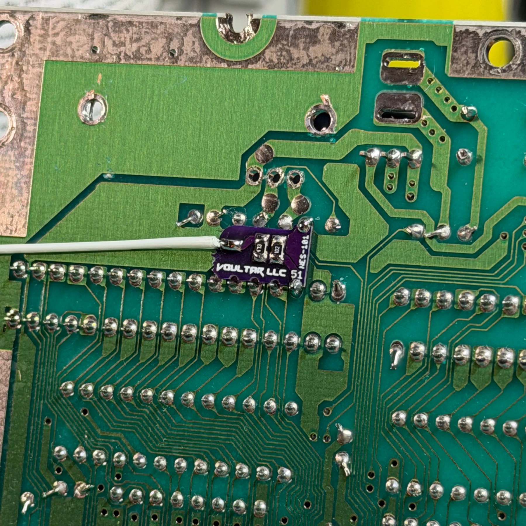
Lastly since the customer wants expansion audio restored I put together a Voultar QSB and wire that up which will connect to the NESRGB mixing point on top of the board. The new NESRGB allows for routing expansion audio into pads 45/46 on the new V5 but I had a discussion about the V5 with George from 1UpRestorations earlier and he confirmed there are issues with this new method and audio levels on the Toploader model so he recommended using the old V4 and earlier mixing point and that is how I wired this one up. To finish the NESRGB install I then flipped the board back over one more time and inserted the expansion audio wire into the mixing point from underneath and soldered it in place.
With the NESRGB done it was now time to install the new voltage regulator with some fresh thermal paste, the new AC power jack and secure the heatsink and new multiout panel from LaserBear.
With all that done it was time to partially reassemble the system (leave top shell off) and hook up a SNES RGB CSync cable and test along with composite and s-video using another spare cable I have. All video signals worked and audio sounded good so I fired up the Japanese version of Castlevania III and confirmed expansion audio sounded correct, everything was working properly!
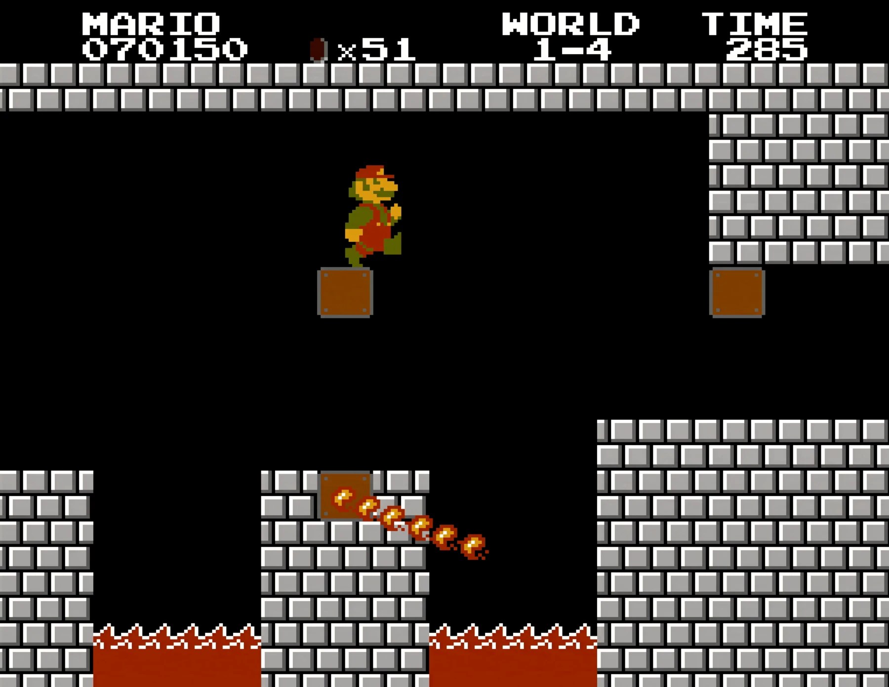
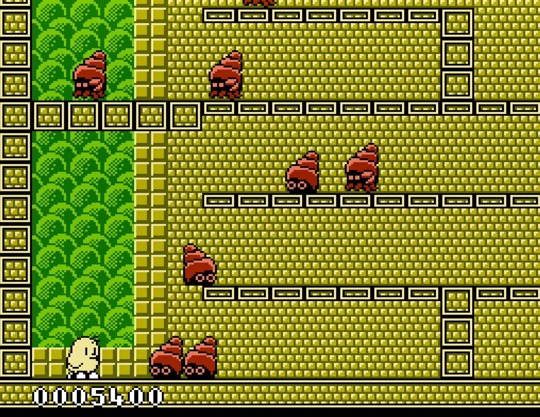
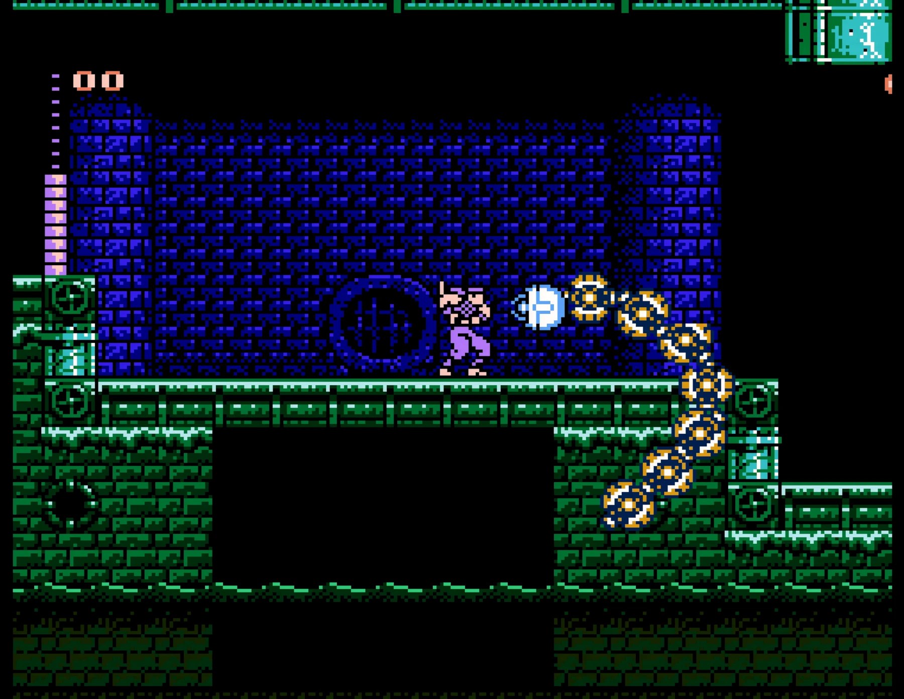
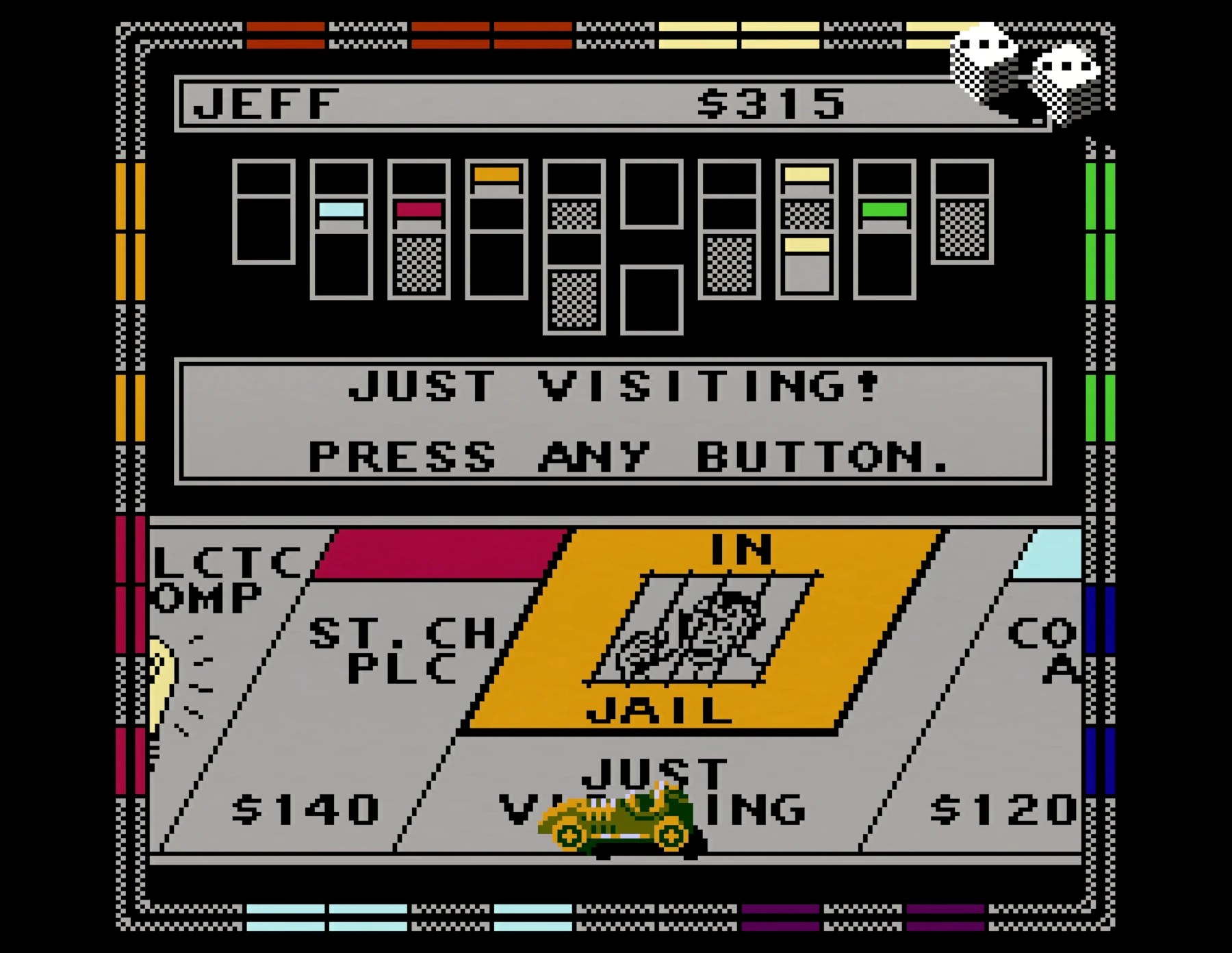
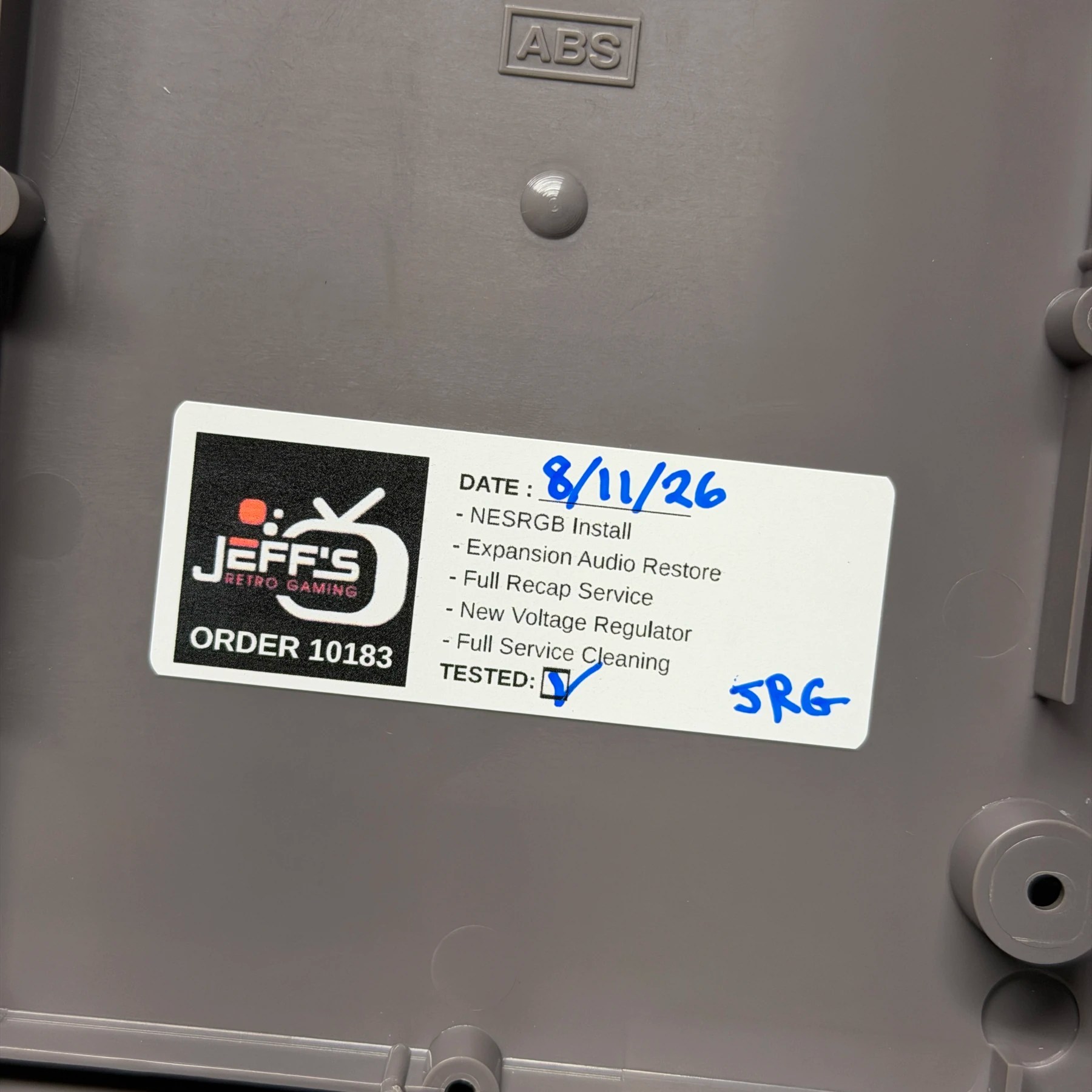
Put a sticker on the bottom inside shell and finished the full reassembly, then gave the outer shell one more wipe down and a nice coat of UV protectant spray. Got my staged shot in front of the PVM and then some 4K captures (as seen below) via the RetroTink 4K and Elgato4KX!
I did observe some strange ringing on a specific unshielded cable in my setup but after process of elimination it ended up being related to my SVS switch so I’m working to figure out a solution going forward as I work on a lot of consoles and do a LOT of captures. Either way knowing the NES itself was good, got it packed up and ready to ship back (along with an RGB cable they purchased to pair with it)
Another NESRGB in the books!