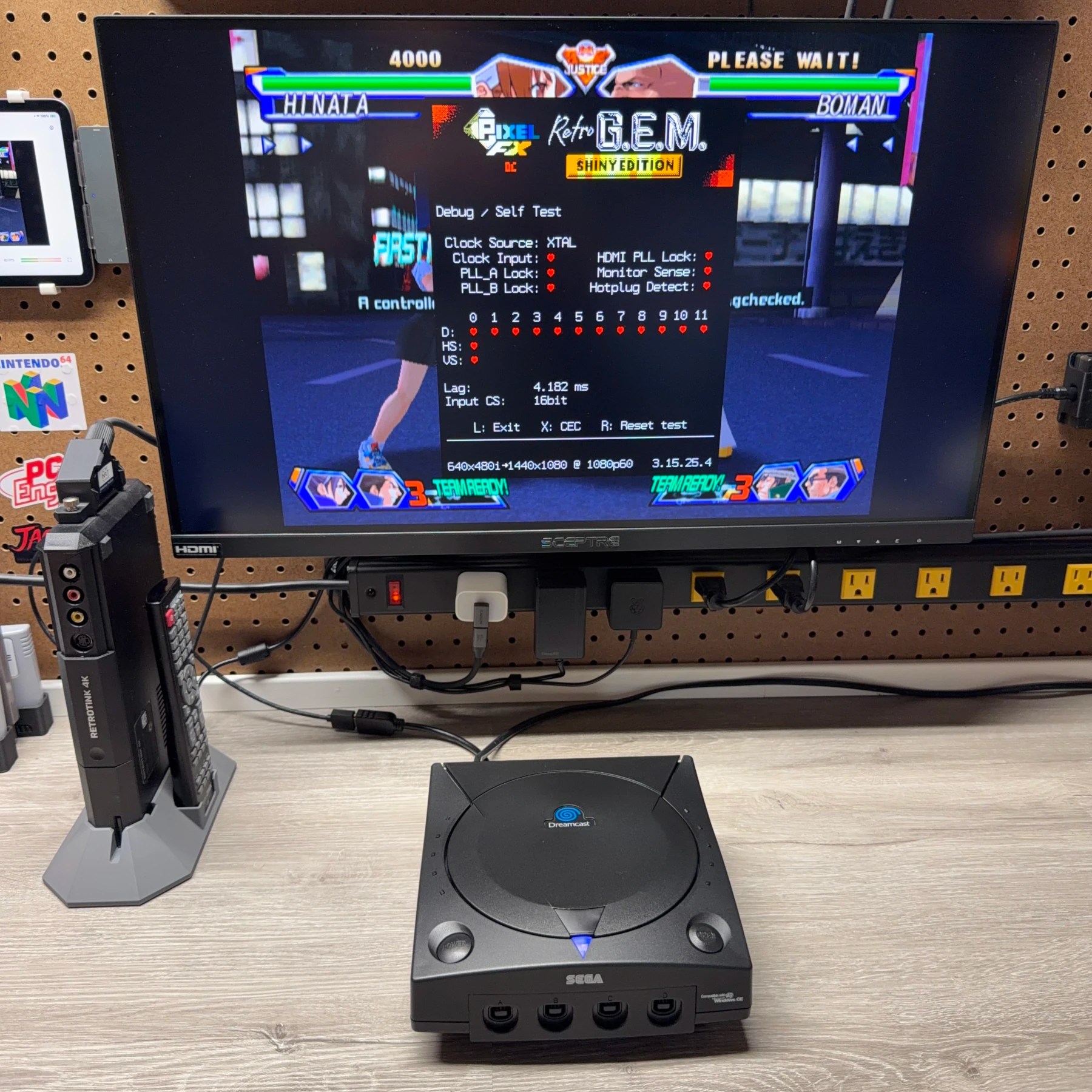
Console #3 for the upcoming Expo is this completely refurbished and custom Sega Dreamcast! Someone generously donated this aftermarket shell to me and I thought it would make for a great build along with a matching blue LED and GDEMU mount printed in blue so I have kept this in my back pocket and now that I had a spare VA1 board for the build, it was a great chance to make use of it! I have actually had someone reach out who is attending the Expo and ask if I would hold this for them there so I think this build is already accounted for but if that falls through and ends up not selling at the expo it will be listed on my site sometime soon after!
With a PixelFX Shiny HDMI mod, ODE solution, silent fan and full refurb this thing is looking sharp and ready for a long future! Doesn’t hurt that the Dreamcast is also a personal favorite of mine and a breeze to work on so these are always enjoyable projects 👍
Knowing this was going to get a full refurbishment on top of the mods I always like to complete those first and test before introducing any variables in the form of upgrades. Since the drive was being replaced with a GDEMU, no reason to clean or recap that at the moment, instead it will be put into the spare parts bin and eventually refurbished to see if it’s functional for a future build or spare for a customer send-in unit!
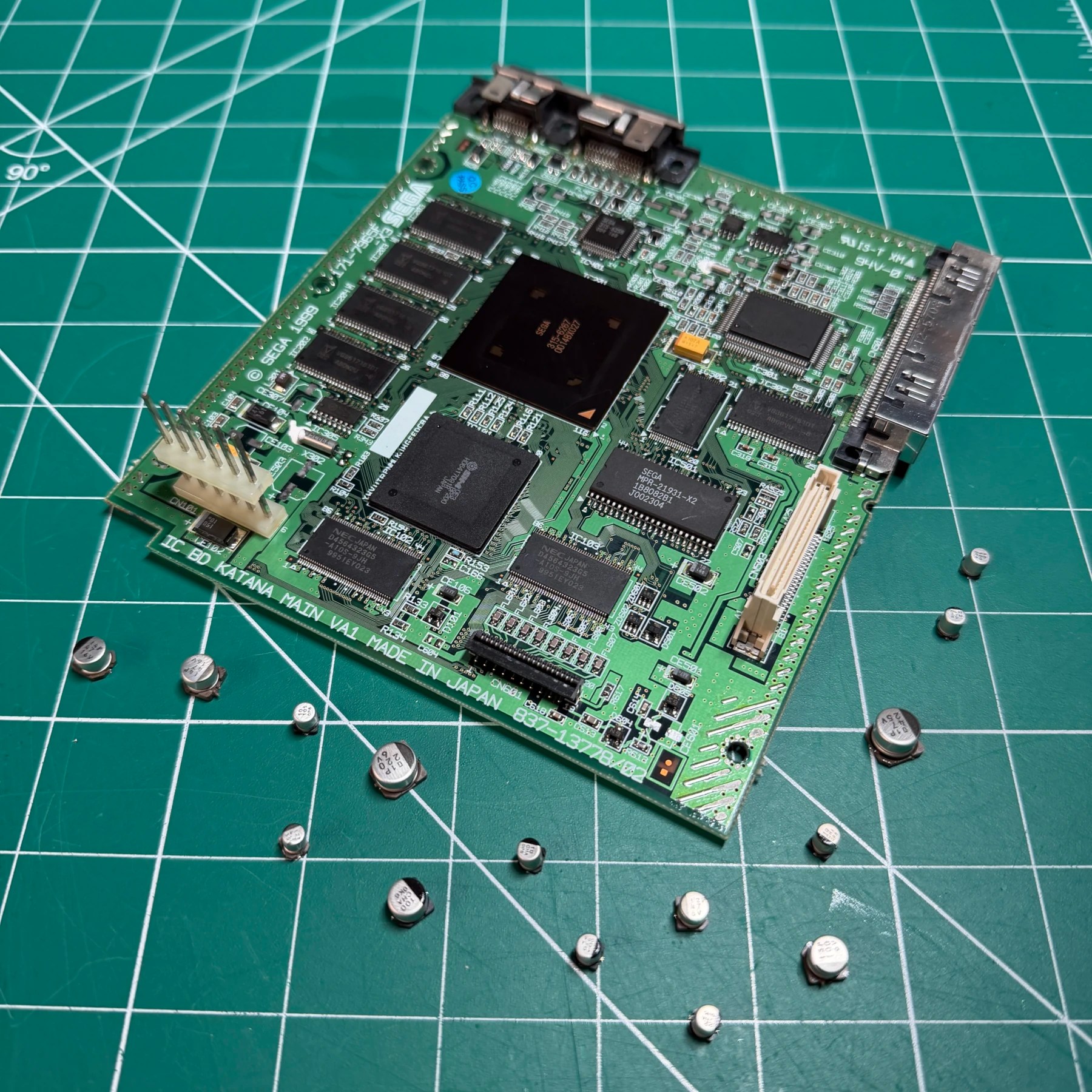
Since the shell was new/aftermarket there was no cleaning on that front so I began by tearing down all the components to the bare motherboard and then used my hot tweezers to remove all the SMD caps located on it. I then scrubbed the top and bottom of the board, prepped the pads and soldered on all new caps using the VA1 Console5 cap kit.
There was some oxidation on the PSU pins of the motherboard so I did clean those thoroughly with a wire brush and then some ISO on a microfiber until they had a perfectly clean shine.
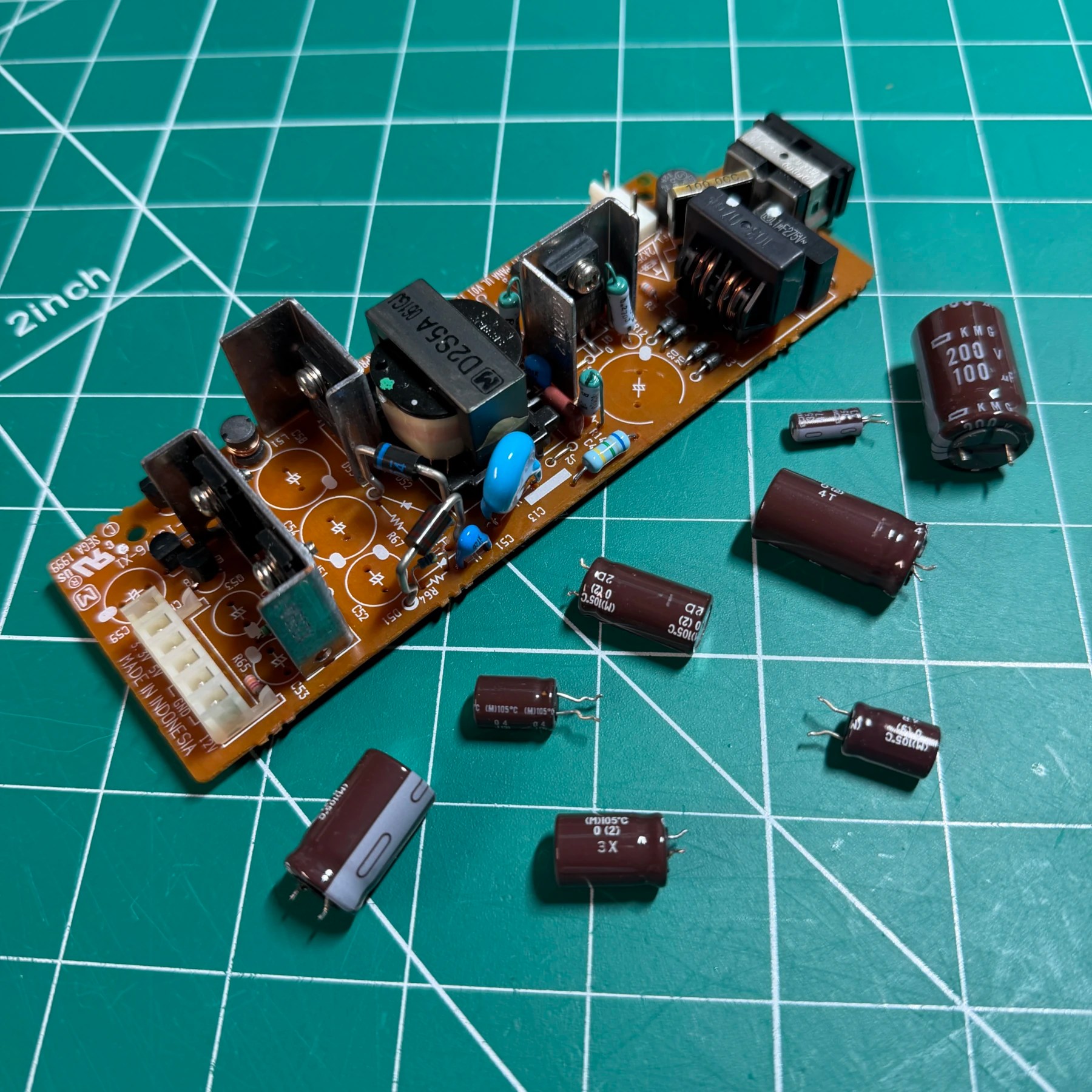
The next item to refurbish was the PSU. For this, I removed all OEM capacitors, deep cleaned both side of the board, installed the new ones from Console5 then cleaned up any unspent flux.
I also reflowed the joints near the rear power connector and use a small wire brush to clean inside the PSU connector terminals as its imperative the Dreamcast always has a really solid connection to the PSU or it can exhibit strange behaviors like freezing and crashing. Once all the above was done since I knew I was installing the 12V dummy load on the GDEMU itself (I sometimes do on the PSU) I set that aside and moved on to the last refurbishment piece – the controller board!
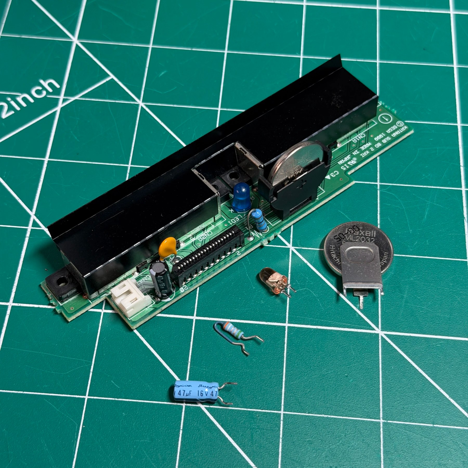
This one got a new socketed ML2032 battery for keeping date/time, a resettable fuse so if a controller is inserted/pulled during use and blows it you can simply reset to restore function. Lastly the single capacitor on that board was replaced and I reflowed the fan connector (which can crack and cause issues) and swapped out the stock orange LED for a blue one. This LED matches the aftermarket shell swirl logo and really pops on the black shell!
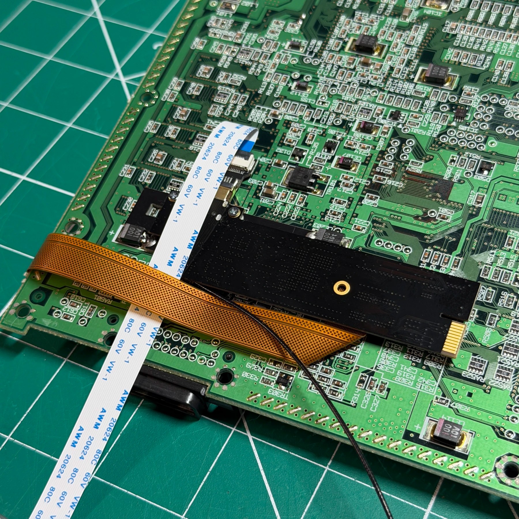
Now it was time to begin the most time consuming mod, the HDMI install. For this I simply follow the guide and set the jumpers, soldered the underside bracket on and then flip the board to prep the main flex install.
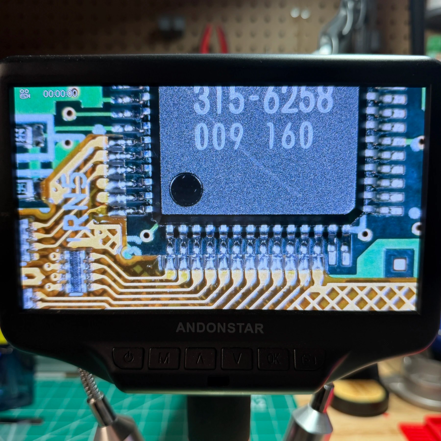
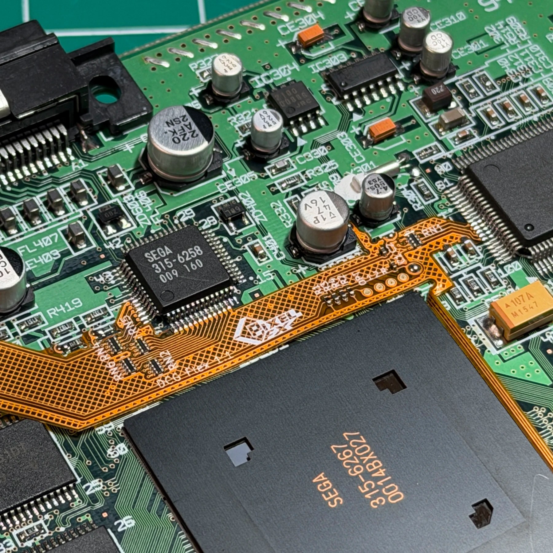
It’s always helpful to reflow the ASIC pins you will be connecting to so I do on both chips as well as remove the resistors for the flex install and reflow/tin any other connection points like for the reset pad or the controller pads. For aligning the flex I find it best to align the L shaped portion against the DAC and ensure its centered on all the pins and tack on the outer 2 on each side. The connection to the audio chip will naturally line up correctly if this first step is done so once the flex is tacked on the outsides to both, I add a bunch of flux and drag solder across the pins a few times to ensure a solid clean connection.
With that done, I make quick work of folding the flex and soldering to the reset and controller points to finish up the topside install, as well as the connection to the previously removed resistor pads and few other points near the DAC and audio chip.
With this all done I fold the flex over gently around the board, bend and fit it to the GEM board then mount that one final time on the underside. I prefer the no-cut mod on consoles when possible and since barely anyone uses the serial port it makes sense to remove that and use a mini hdmi port in its place. For removing that port I simply flow in some low melt solder and then lift the serial and AV ports off carefully, cut them apart and then solder just the AV port back on after cleaning up all the low melt. Im then able to connect the GEM hdmi flex to the board and then new HDMI port and set to the side for the moment.
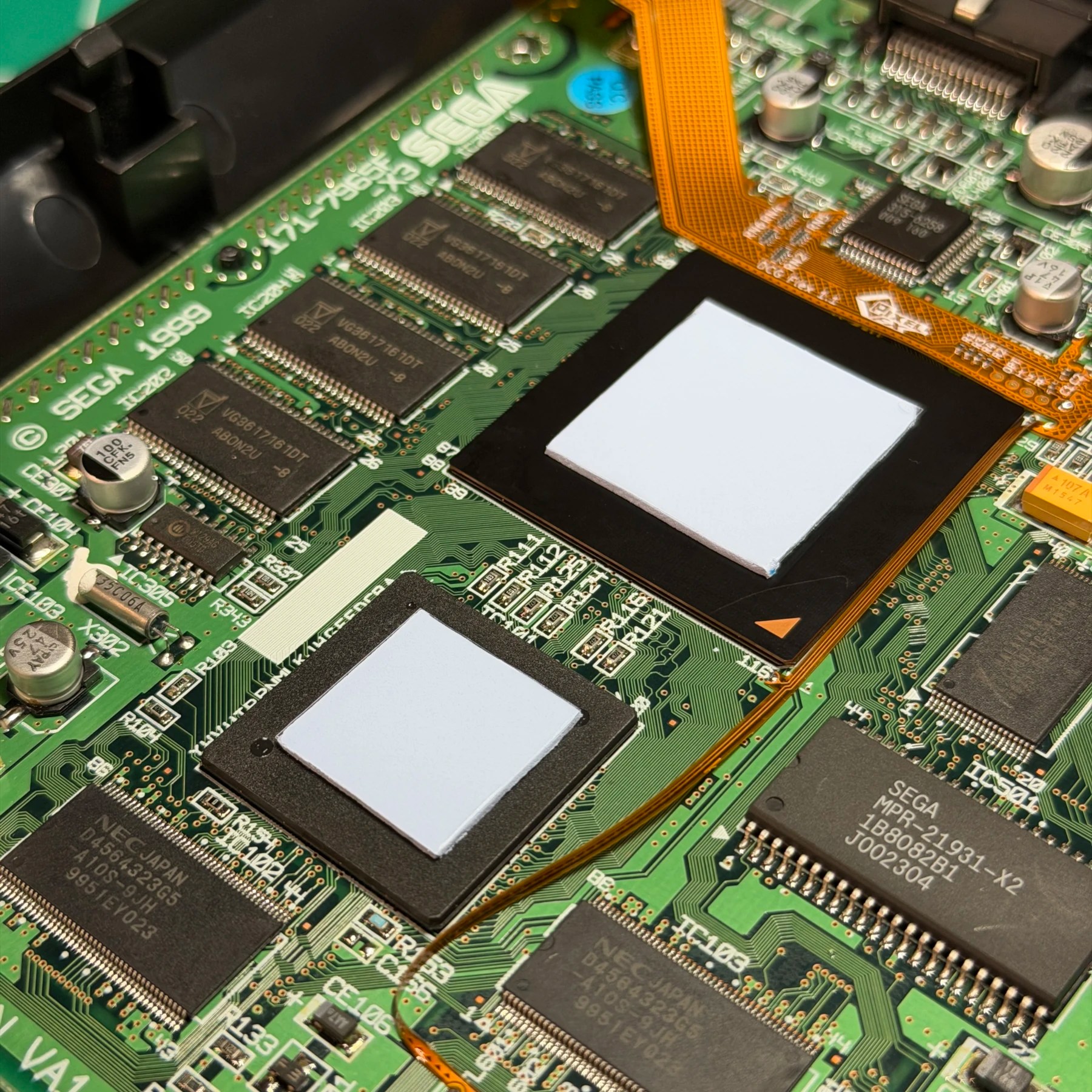
Before I can start reassembling I cut and attach brand new thermal pads (Arctic MX) to the underside points and 2 for the chips on top, then also attach a single 30AWG Kynar wire to the OPT pad on the GEM which will connect to the GDEMU I’m installing shortly. Since the last 2 upgrades do not need access to the board underside it’s a good time to reinstall the bottom shield and mainboard, then the top shield once the thermal pad protective plastic is removed.
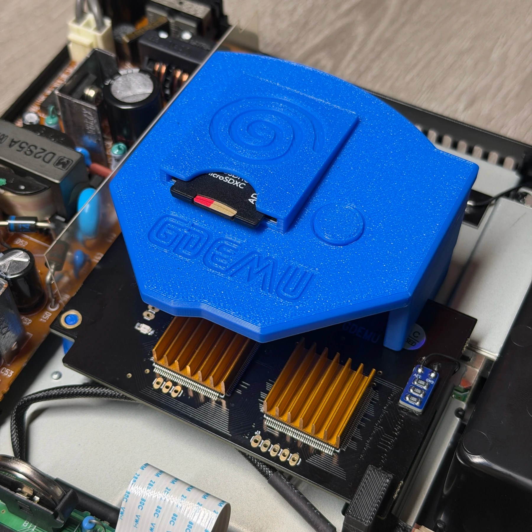
Knowing the GDEMU install is coming up I send a copy of the mount I want to use to my printer and let that run while I do the rest. This involves attaching one of my 12V dummy load boards to the GDEMU and wiring it up, then also attaching the options wire from the GEM. Once the mount finishes printing I remove the plastic cover of the SD card extender and snap fit it inside the mount and assemble the mount and put the heatsinks on both chips of the GDEMU (comes in the kit)
At this point, the GDEMU is done I just print an anchor brace from GamerGhosts which holds the front corner down as these are notorious for bumping loose during transport and causing issues, so this handy arm holds it nice and secure!
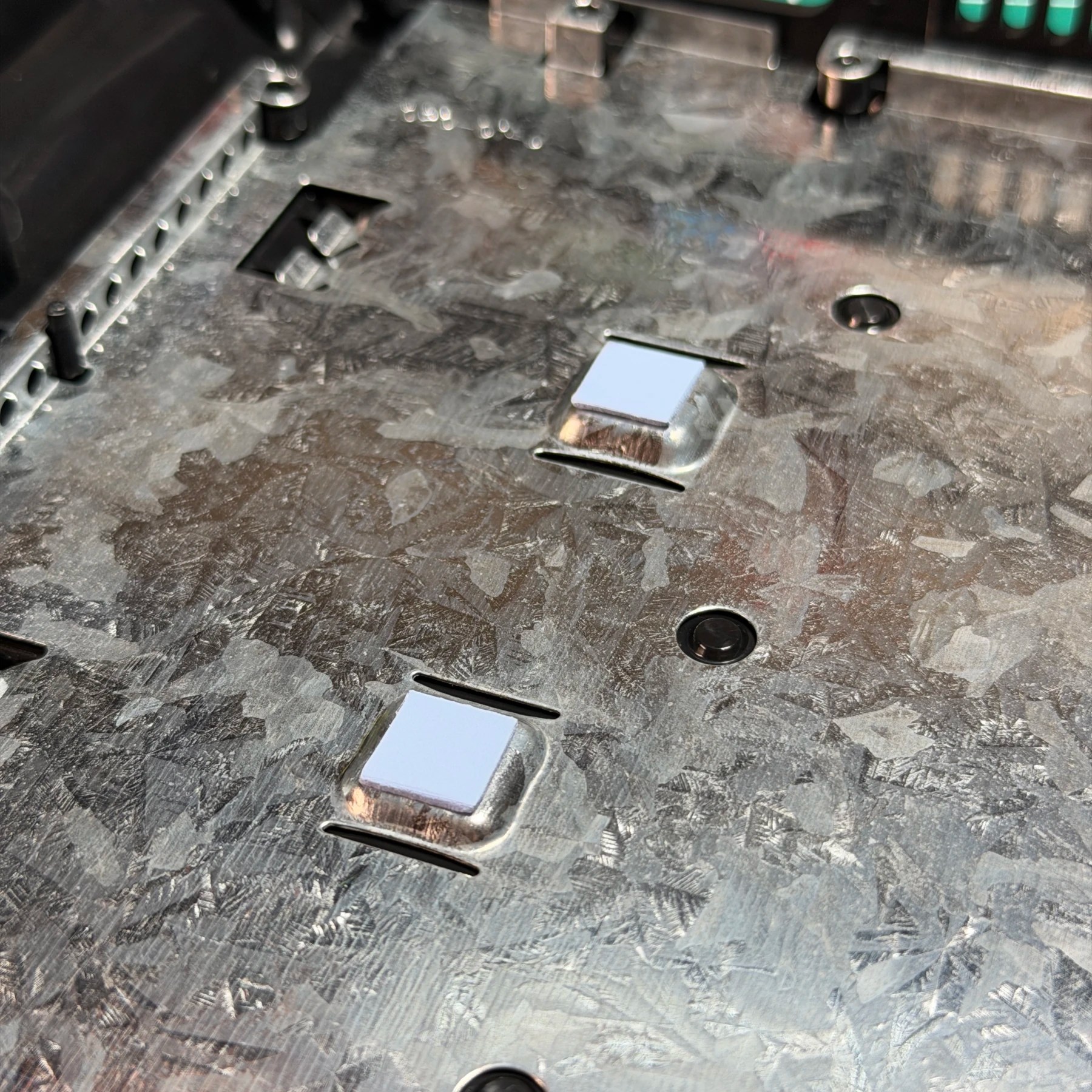
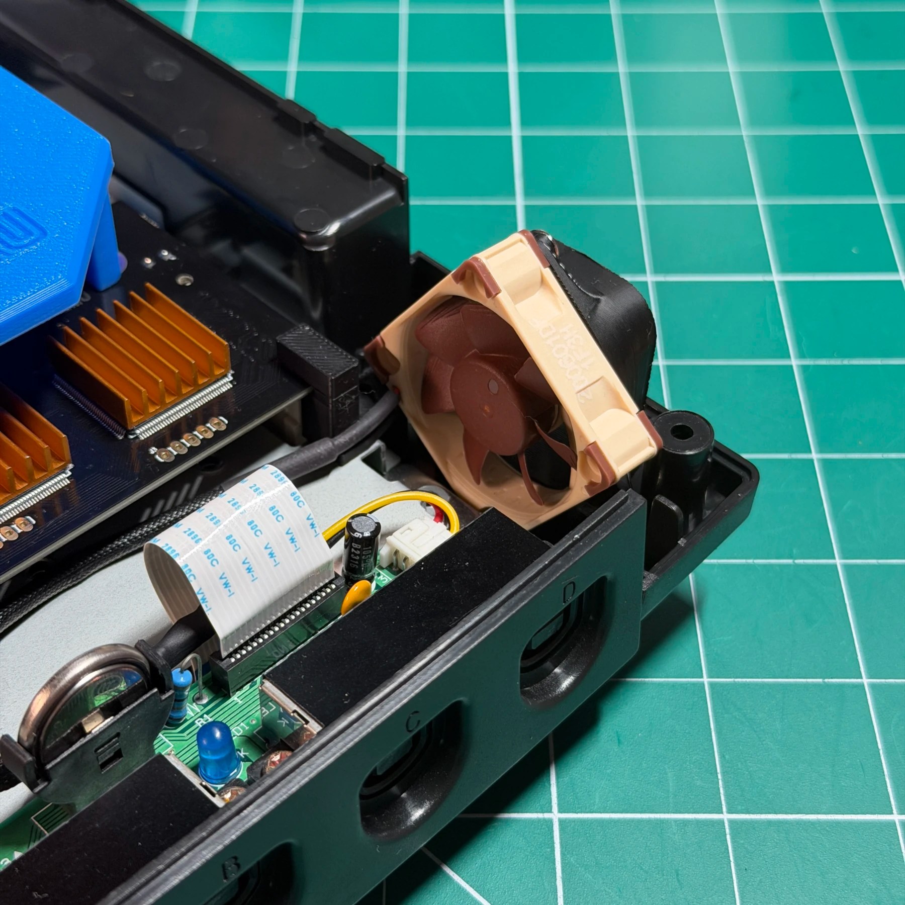
One of the most annoying things about the DC is the ridiculously loud fan. I had a spare Noctua kit on hand so I stripped and spliced the Noctua connector with the DC fan connector and added a 10K resistor across the red and yellow wires for proper detection by the Dreamcast. These are a HUGE upgrade on the system and night and day difference volume wise. Only other thing required for this is a 3D printed shroud and custom tray open lid assembly because the fan is a lot bigger. I have these STL’s on hand already so print them out in black, then installed the fan and get everything connected. Before signing off on the work I hook up the PSU temporarily and ensure it boots, loads the RetroGEM and GDEMU (with my sample SD card) and then join the Wi-Fi and do all the firmware updates I can. I let it run in the menu for several hours on the debug / health screen and play some games to get the 4K captures and all looks good!
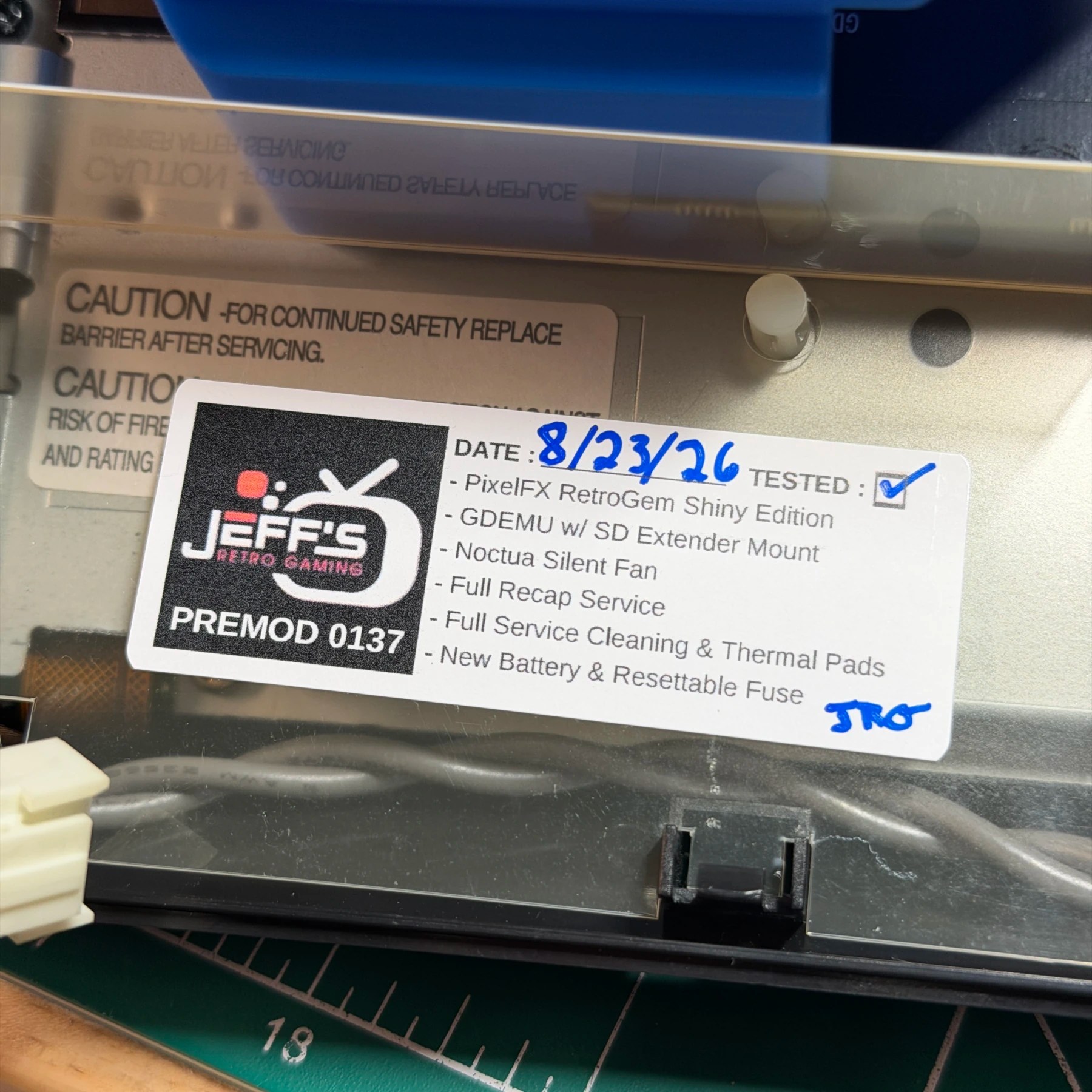
Final step is to add my sticker and close up the shell. Another sleek console all decked out and refurbished and ready to find a new home 🫡