
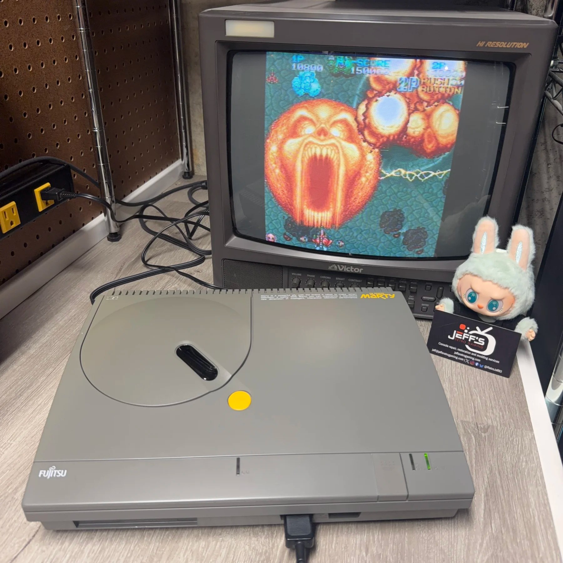
I’ve had a decent number of Marty’s come in over the last few years all needing a Full Recap Service at minimum but almost all of them exhibiting some of the trademark signs. No power, low or crackling audio, power but black screen. This unit matched the latter behavior where power LED would come on, monitor would detect NTSC sync signal but no Marty splash screen, starfield intro or sound.
I’ve had this exact scenario come into the shop before and be fixed with simply a recap and cleaning but there is no guarantee, as I would find out on this one…
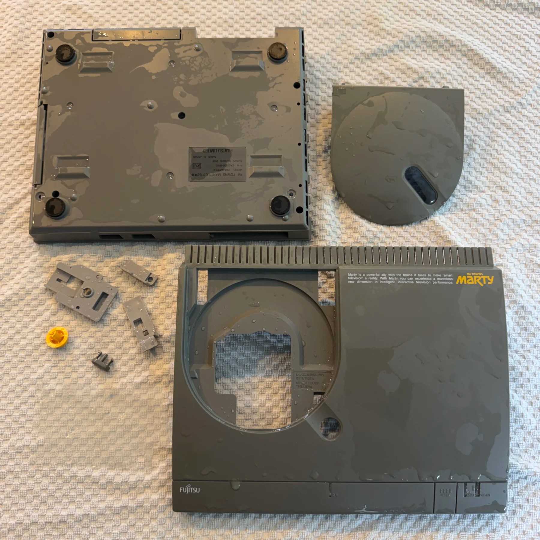
After testing to confirm the black screen issue, I fully disassembled the Marty (which is quite a chore) down to the shell and set all those plastic parts aside to soak and wash, then left to dry overnight. While waiting for that I began my modular approach to recapping and cleaning the Marty which is in the order of PSU, then CDROM, then mainboard and finally the FDD.
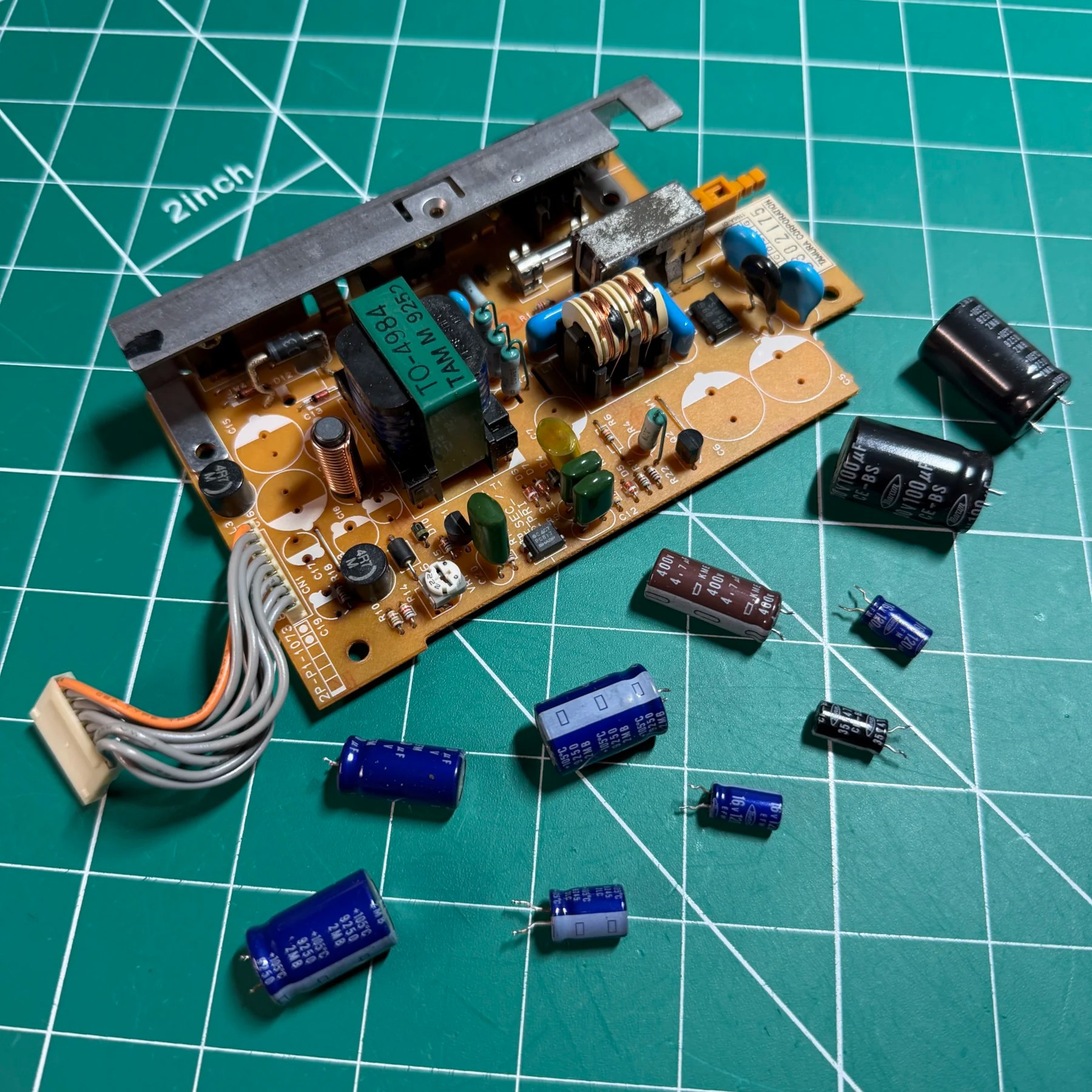
I immediately noticed several leaking caps on the PSU which had stained the area near the 8-pin mainboard connector. Didn’t think much of it except thoroughly cleaning the board but as I was cleaning the connector and nearby area, PIN 8 (ground) pulled right out of the connector socket with barely any pressure. From what I could see on the end it appeared to just be an old brittle wire strand that finally gave out, so I stripped some of the wire sheathing back, tinned and soldered it to the underside of the board (turns out I was NOT done with this CN8 connector yet…) and then finished the full PSU cleaning and installation of all new Console5 caps.
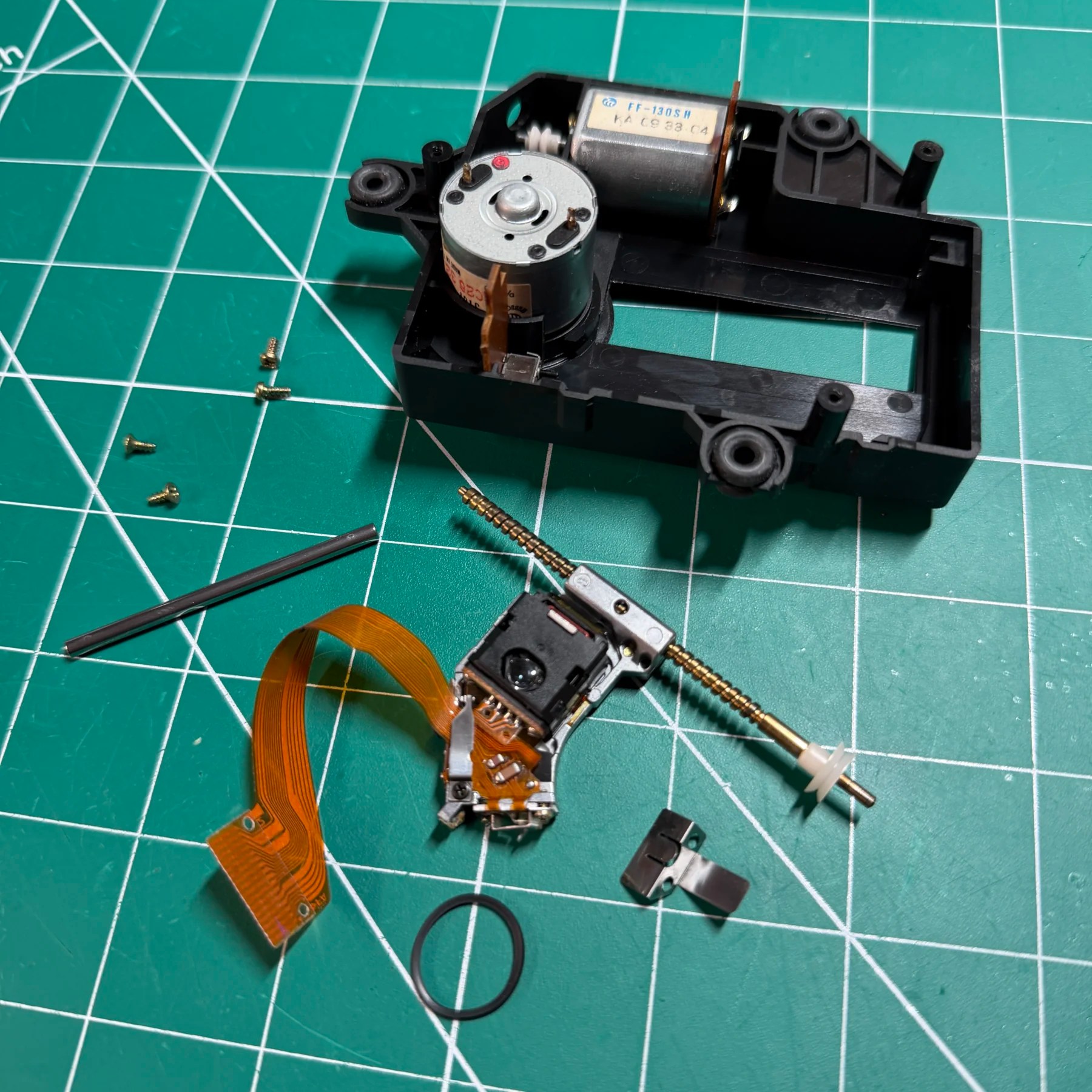
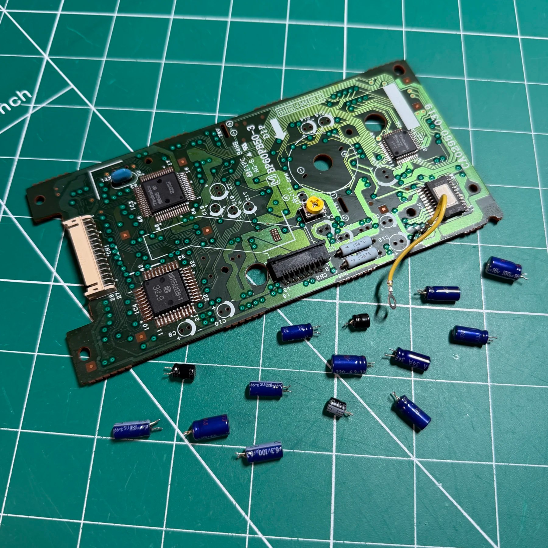
Setting aside the PSU I moved onto the CDROM which requires unscrewing the laser assembly cover and desoldered a few vertical joints then removing a plastic cover protecting 4 caps near the moving laser sled to access all the through hole caps on this board. No surprises here though, got them all removed, deep cleaned the top and bottom of the board and then installed all the new caps from Console5. When removing the originals pay attention to a few of the lower profile ones as there are some clearance issues here!
With the PCB finished I then took out the laser assembly itself, cleaned and greased the rails and contact points and checked the belt health. All looked good on that front so I reassembled fully and cleaned the lens then attached the optical drive back to the PCB and set that aside with the PSU.
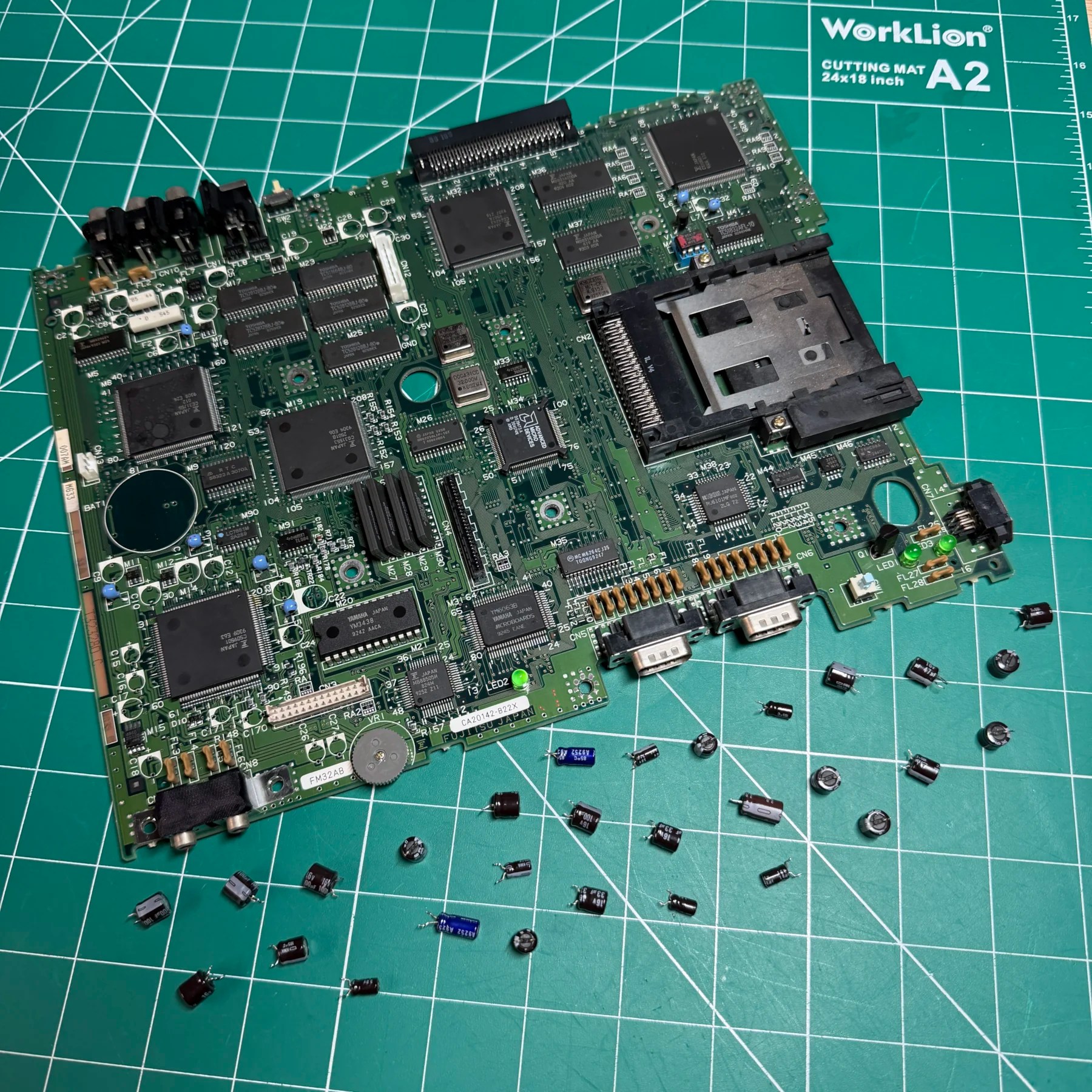
It was now time to turn my attention to the mainboard which is where the bulk of the caps (and work) is put in on these. I first took a cursory glance in the lower left area near the audio amp as C22 is known to leak on all these and it can cause a ton of board damage. I saw the telltale signs of leaked fluid and some corrosion but not nearly as bad as some of the others I’ve repaired so I removed that first, then worked my way clockwise around the board until all the caps were taken off.
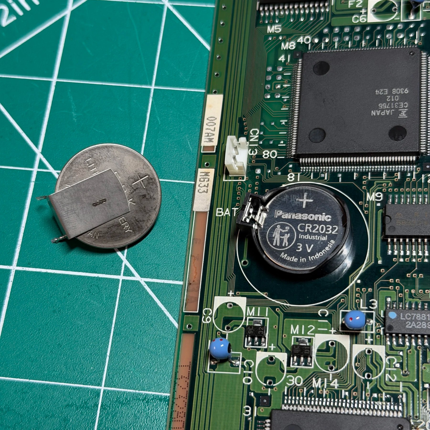
With those out of the way I also removed the battery since they chose the replacement service and cleaned the entire board top and bottom. I then soldered in a CR2032 holder and all the new caps from Console5 after testing the cap via’s and traces in the C22 area of the board to ensure continuity and no missing/rotted traces. With the mainboard recapped I moved on to the FDD.
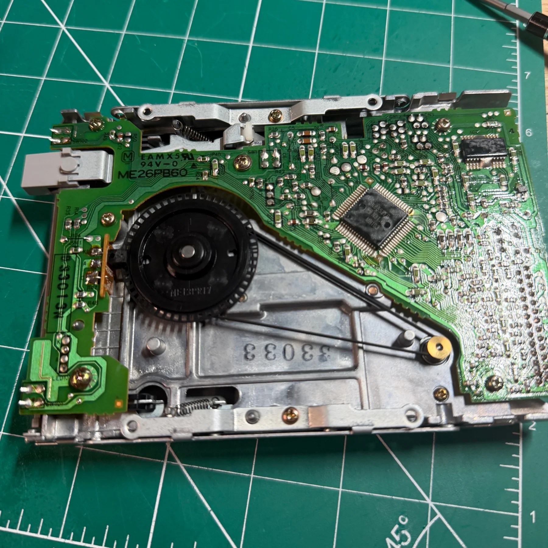
For the FDD there are only 2 capacitors on the drive board to replace plus a new belt. So I unscrewed and carefully lifted the PCB up to gain access to remove both caps and be able to lift the old belt off the wheel which was intact but barely, very loose.
I installed the last 2 caps in the kit from Console5 and then placed the new belt around the large drive wheel and dropped the PCB back in place and screwed it in. After spinning the motor spindle a bit to ensure the new belt was fitted correct and operating I wrapped it up on the FDD and reinstalled into the system (which I had been reassembling after each component was complete). At this stage I would be able to fully test the console before reassembling top shell and signing off on it with a sticker, so I plugged it in and… same black screen, no change in behavior.
Stumped I got back into the mainboard and looked around C22 and the main ASICs. I noted a few ASICs had some pretty dull/cold looking joints so I quickly reflowed the entire affected chips and still no change. Got out my microscope and started probing every single via, joint and trace near C22 (which I removed temporarily for easier access to the area).
After a good hour of toning out various points I believe I had found the culprit. Nearby the M27 DRAM module I found a trace that I had missed earlier and also one trace near C22 (R71 connection to a via) which I had also missed. I noted those two and then still checked all other vias and traces in the entire region so I could do all repairs at once, but those were the only two I found.
Believing the culprit of the black screen was identified I carefully scraped and exposed the copper via on both sides of the damaged trace and ran a small 30 AWG Kynar wire through each via and soldered it on the underside of the board. With a multimeter I verified continuity and then proceeded to clean up my unspent flux and reassemble for another test…
This time I saw the splash screen and the starfield intro with music! Great news I thought but just to be sure I powered off and back on a few times and noticed something very strange now… It would boot up correctly 3 out of 4 times, the other times it would now not even power on when pushing the button the PSU, at least before when I didn’t get the bios screen I would see power and activity LED’s on the front of the system but not now.
That’s when I went to go lift the PSU back out and felt a few of the wires were loose… With a very small amount of tugging Pin 2 on CN8 just popped right out like Pin 8 earlier! and Pin 1 felt very loose. These both drive 5V on the system and could absolutely explain the power issues so presumably both joints were failing or on the verge of failing. Deciding it wasn’t worth trying to save the connector and there’s really no need for it (since you disconnect the mainboard side anyways) I desoldered it from the PSU board, snipped and stripped all 8 wires back and soldered them through the top and to the bottom of the PCB directly with nice solid clean joints.
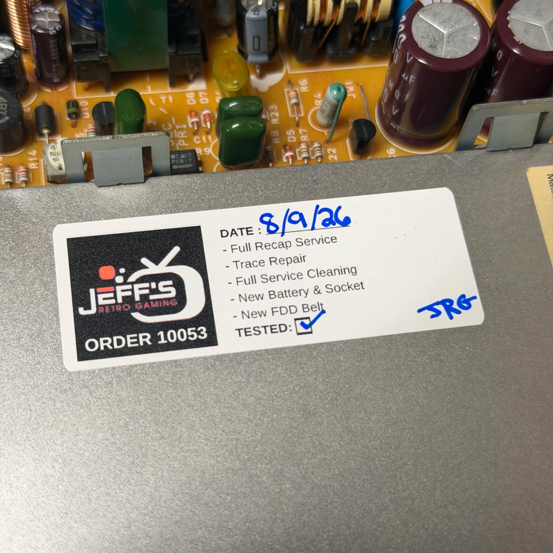
After cleaning up the board I reassembled and now it was booting and working properly every time. I then proceed to test the FDD with my copy of Dragon Slayer (which worked!) and the CDROM with my copy of Truxton II (which also worked!) so I finished the top shell assembly, added my sticker and closed it up and left running on the bench for several hours playing the disc.
This one was a bit more of a pain but I could have saved a little time if I had been a bit more thorough in the area of C22 (which I know is suspect). So, lesson learned for the next Marty with this issue!
Either way, glad to have this done and shipped back to the customer!